Chapter 2 Assembly & Installation
Revision W HF Series X-ray Generators - Service Manual
2-22 Quantum Medical Imaging
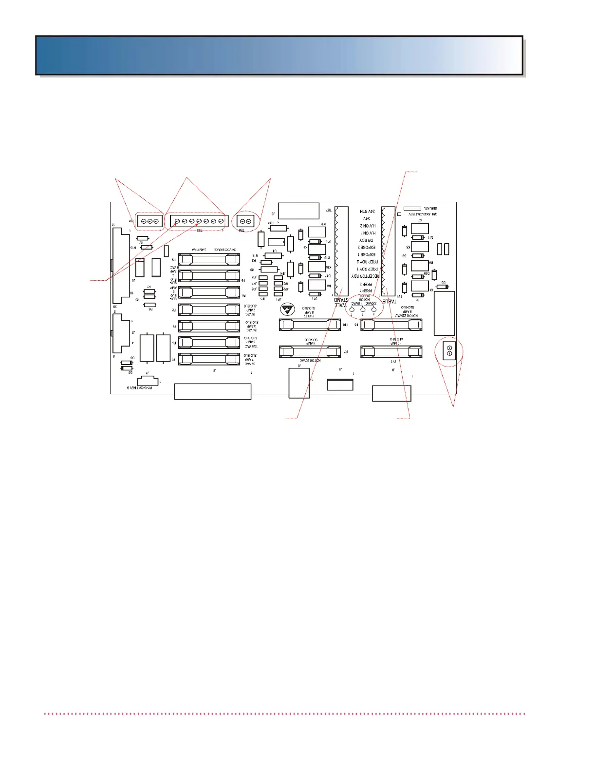
Figure 2-16. Digital System Interface Board A9 - Connection Locations
Door Interlock Switch Connection
To wire a door interlock circuit, remove jumper and connect door interlock
wires (supplied by installer) to terminal block TB6 pins 1 and 2 on Interface
Board A9 [(P/N AY40-023T/or AY40-061T on internal high-speed starter sys-
tems) or (AY40-034T/or AY40-062T on internal high-speed starter systems)].
See Figures 2-15 or 2-16 for terminal board TB6 location. When the door is
closed, the circuit will be continuous (contacts closed).
"In Use" Light Switch Connection
To wire an "X-ray On" or "In-Use light", connect wires from light circuit (sup-
plied by installer) to terminal board TB5 pins 1 and 2 on Interface Board A9
[(P/N AY40-023T/or AY40-061T on internal high-speed starter systems) or
(AY40-034T/or AY40-062T on internal high-speed starter systems)] (On
AY40-062T boards, pin 3 is not used). See Figures 2-15 or 2-16 for terminal
block TB5 location. When the X-ray generator is in either PREP or EXPOSE
states, the circuit will be continuous (contacts closed).
1
24VAC
24VAC
CH GND
24V
24V RTN
SPARE
COLL RDY
15V RTN
15V
GND
D2
D4
D7
D8
D12
D13
D14
K3
R11
R12
R16
R17
R19
TB5
D20
D19
F18
F19
F13
DOOR INTERLOCK
TERMINAL BLOCK TB6
TUBESTAND
TERMINAL
BLOCK TB2
COLLIMATOR
CONNECTIONS
TERMINAL BLOCK TB1
EXPOSURE
HOLD
CONNECTIONS
(AUTO COLL.)
X-RAY ON LIGHT
TUBE ROTOR BOOST
VOLTAGE JUMPER
BOARDS ONLY)
WALL STAND BUCKY POWER
TERMINAL BLOCK TB7
 Loading...