Chapter 2 Assembly & Installation
Revision W HF Series X-ray Generators - Service Manual
2-14 Quantum Medical Imaging
b. Connect mains line and neutral wires to TB1 terminals L1 and L2,
respectively. Do not turn mains power on at this time.
4. On three-phase systems:
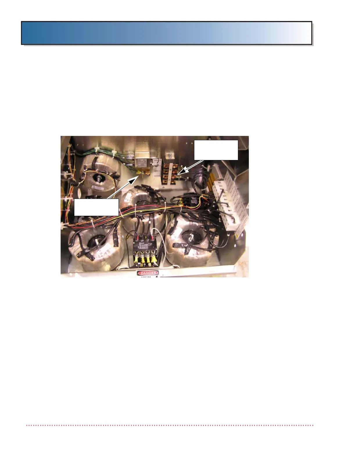
a. Connect Phase A, B and C wires to TB1 terminals L1 through L3,
respectively. Do not turn mains power on at this time. (See
Figure 2-9).
Figure 2-9. Ground Lug and Terminal Block TB1 Locations
b. If available, connect Neutral wire to TB1 terminal L4 (N). (Neutral
connection may be required; check local electrical code.)
5. On STORED ENERGY (SE) type generators, the battery tray fuse(s) are
shipped in the non-inserted position to minimize battery discharge and
high voltage hazards. With fuse in holder, close the fuse holder(s). The
SE system can be plugged into a standard switched 115/230 VAC
grounded receptacle. The switch controlling the receptacle should be
within reach of the operator control console. For 115 VAC installations, a
25-foot power cord with a hospital-grade plug is factory pre-wired to the
generator. For 230 VAC installations, a 25-foot "HAR" power cord is fac-
tory pre-wired to the generator.
If power cord is replaced, ensure that impedance between the protective
contact in the mains plug and any accessible metal part which is protec-
tively earthed does not exceed 0.1 Ohms.
GROUND
LUG
TERMINAL
BLOCK TB1
 Loading...