Chapter 2 Assembly & Installation
HF Series X-ray Generators - Service Manual Revision W
Quantum Medical Imaging 2-9
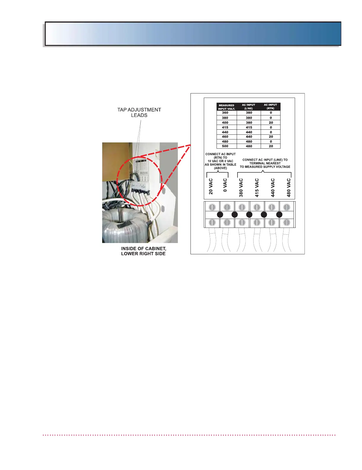
Figure 2-4. Single-Phase 380 - 480 VAC Single-Phase Input
AC Transformer Line Tap Connections
4. For single-phase non-SE models, it is necessary to insure that the line
resistance meets the maximum allowed as stated in Chapter 1, SPECIFI-
CATIONS. If line resistance exceeds the specification, the generator must
be derated. Refer to Chapter 3, CALIBRATION for derating instructions.
5. Verify Line Monitor Board A8 "line input jumper" is configured correctly
based on the installation site’s measured line input voltage as follows:
a. For 208 - 260 VAC input models (QG-25, QG-32 and QG-40), refer to
Line Monitor Board A8 (AY40-022T1) Test Point/Jumper Location Dia-
gram in Chapter 6, DIAGRAMS and, if necessary, set "line input"
jumpers to match the line input supply voltage (i.e., 208 - 260 VAC,
three "240" jumpers are installed). Also, for 208 - 260 VAC line input
configurations, fuses A8F1 and A8F3 should be 1/2A.
b. For 380 - 480 VAC input models (QG-25-5, QG-32-5 and QG-40-5),
refer to Line Monitor Board A8 (AY40-022T2) Test Point/Jumper Loca-
tion Diagram in Chapter 6, DIAGRAMS and, if necessary, set "line
input" jumpers to match the line input supply voltage (i.e., for 342-
403 VAC input, install jumper"380"; for 404-459 VAC input, install
jumper "430"; for 460-528 VAC input, install jumper "480"). Also,
for 380 - 480 VAC line input configurations, fuses A8F1 and A8F3
should be 1/4A.
 Loading...