HF Series X-ray Generators - Service Manual Revision W
Quantum Medical Imaging, LLC A-15
Appendix A AEC Calibration with DR or CR Film Plate
decreasing the AEC REF value shown in the AEC
Optical Density Calibration Screen (see Figure
A-4).
IMPORTANT! Following a calibration procedure,
unless the "Save Calibrate" or "Measure, Cali-
brate" key is pressed, no change is made to the
currently saved calibration value(s).
18. Re-locate the DR receptor to the most commonly used receptor cabi-
net (this cabinet’s ion chamber should be connected to WALL#1 con-
nector A11J2 on AEC Control Board).
19. Press the key next to the Next Calibrate field to advance to Reci-
procity Calibration.
20. The Reciprocity Calibration Screen is displayed; however, this calibra-
tion procedure is not necessary with systems equipped with digital
receptor.
21. Press the key next to the Next Calibrate field.
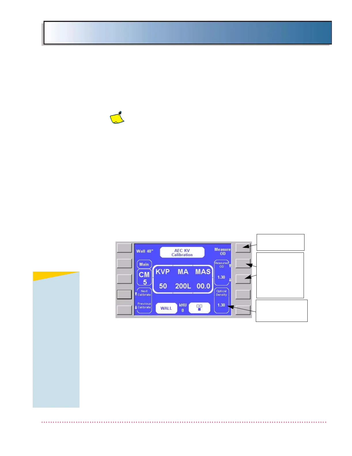
22. The AEC KV Calibration screen is displayed.
Figure A-6. AEC KV Calibration Screen
23. There are a total of six kV calibration points for a 125 kV system (50,
60, 80, 100, 110, and 120 kV); 150 kV systems require an additional
two kV calibration points (130 and 140 kV). The image receptor and
chamber field settings remain the same as those used in the AEC
Optical Density Calibration procedure.
24. Place indicated thickness of acrylic (5 CM for first calibration point) in
the X-ray beam.
25. Take an exposure at the setting indicated in the center display box
(i.e., 50 kVp, 200L mA).
BASE OPTICAL
DENSITY
SETTING
KVP MEASURE
SELECT FIELD
USE UP AND
DOWN
ARROW KEYS
TO ADJUST
TO CORRECT
VALUE
NOTE
Calibration of the
first step (50 kVp)
is not required as
long as AEC
Optical Density
Calibration
procedure in the
previous steps
was performed
prior to AEC KV
Calibration. A
verification that
the "Measured
OD" is the same
as the "Optical
Density" setting is
all that is
required.
 Loading...