Appendix B Calibration (DiRex System)
Revision W HF Series X-ray Generators - Service Manual
B-18 Quantum Medical Imaging, LLC
2. The system displays the ION CHAMBER Configuration Screen, as shown
in the example below:
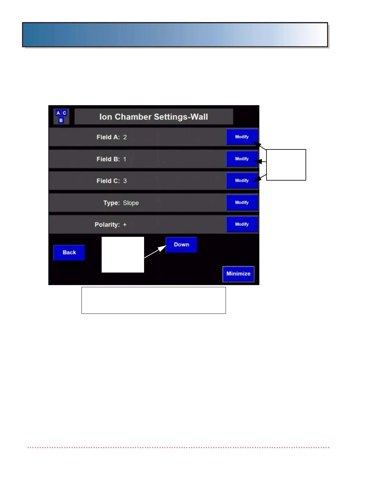
Figure B-12. Ion Chamber Settings Screen
The Ion Chamber Settings Screen displays the assignment of ion chamber
detectors (detector A, B, and C) with respect to the generator’s ion chamber
detector select signals (i.e., FIELD SELECT 1, FIELD SELECT 2 and FIELD
SELECT 3) generated by AEC Control Board A11. That is, assigning "2" to
Field "A" enables detector "2" when the UPPER LEFT chamber detector field is
selected at the Operator Control Panel.
The Ion Chamber Settings Screen also provides settings that facilitate proper
compatibility of the generator with ion chambers that operate differently.
These include Ion Chamber Type (Slope/Level), Polarity (+/-), Output (Nor-
mal/Inverted), and Relay On/Off o settings.
3. Press the Modify button adjacent to the ion chamber detector (Field A,
Field B or Field C) and choose the desired detector setting (1, 2, 3 or
Off).
NOTE: AID ICX-153 or ICX-1153 RIGHT LOAD
USES THIS CONFIGURATION. FOR AID ICX-153
or ICX-1153 LEFT LOAD, SET A=3 AND C=2.
PRESS THESE
BUTTONS TO
MODIFY A
DETECTOR
PRESS TO
SCROLL DOWN
LIST FOR
ADDITIONAL
SETTINGS
 Loading...