Appendix B Calibration (DiRex System)
Revision W HF Series X-ray Generators - Service Manual
B-20 Quantum Medical Imaging, LLC
ber detector A to "3" and detector C to "2". No wiring
modifications are necessary.
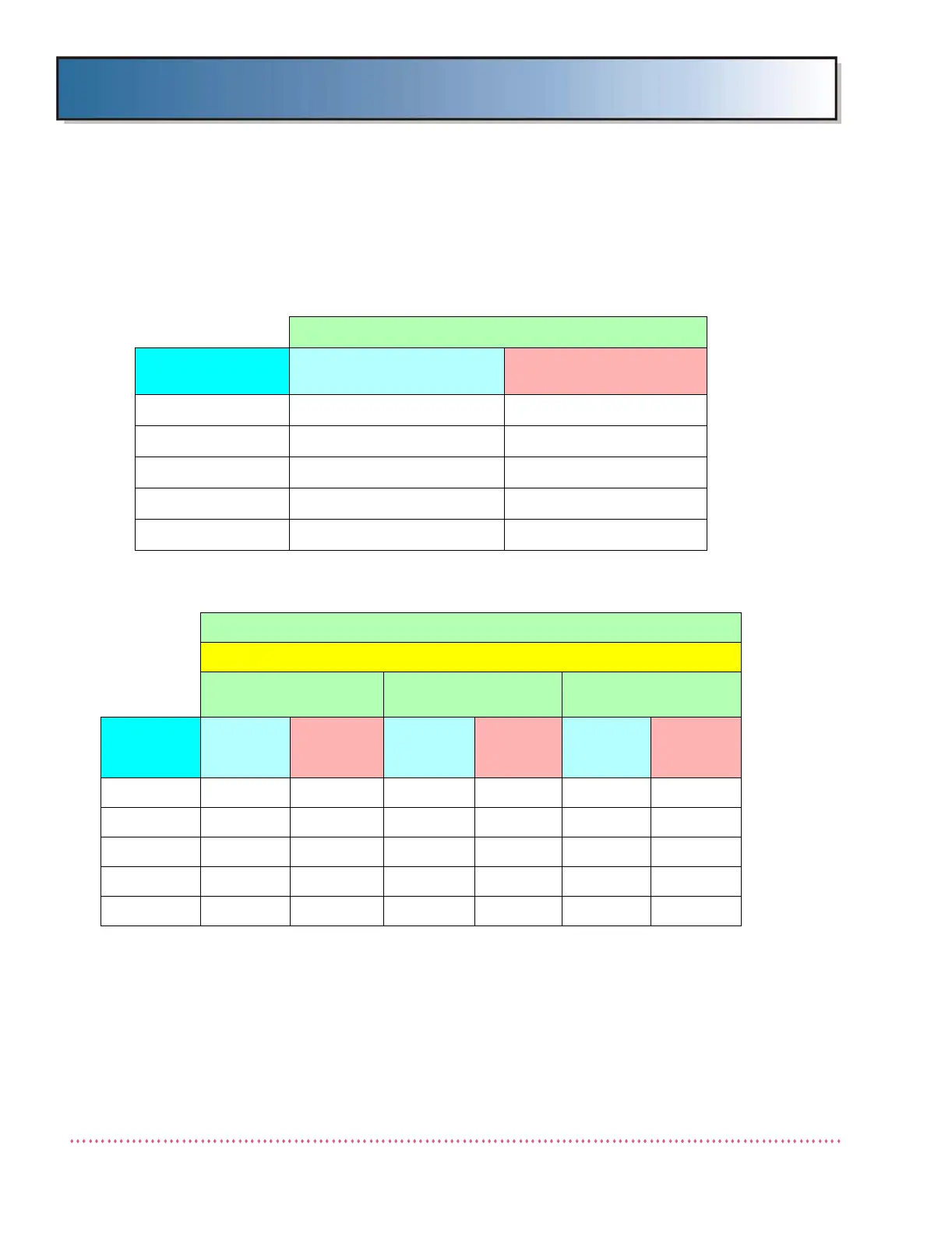
Table 3-2 shows the ion chamber and receptor settings for the generator
when equipped with standard AEC (i.e., Standard AEC Board A11
(AY40-031S) is installed). Table 3-3 shows the ion chamber and receptor
settings for the generator when equipped with universal AEC (i.e., Univer-
sal AEC Board A11 (AY40-027S) is installed).
Table B-1. Ion Chamber Settings for Generator with
Standard AEC (AEC Board AY40-031S)
Standard AEC Systems
Setting Wall Ion Chamber Settings
Table Ion Chamber
Settings
Polarity + +
Wall Relay Off Off
Table Relay Off Off
Invert No No
Slope/Lvl Slope Slope
Table B-2. Ion Chamber Settings for Generator with
Universal AEC Option (AEC Board AY40-027S)
Universal AEC Systems
Ion Chamber Type
Siemens (Level)
AID (Slope)
Tomo Systems
AID (Slope)
Non-Tomo Systems
Setting
Wall Ion
Chamber
Settings
Table Ion
Chamber
Settings
Wall Ion
Chamber
Settings
Table Ion
Chamber
Settings
Wall Ion
Chamber
Settings
Table Ion
Chamber
Settings
Polarity + + + + + +
Wall Relay On Off On Off On Off
Table Relay Off On Off On Off On
Invert Yes Yes No No No No
Slope/Lvl Level Level Slope Slope Slope Slope
 Loading...