Chapter 2 Assembly & Installation
HF Series X-ray Generators - Service Manual Revision W
Quantum Medical Imaging 2-7
WARNING! Approximately 200 VDC is present on
each battery tray. This voltage is live even when
generator cabinet power switch is set to OFF. Use
extreme caution when servicing battery tray(s).
2. On stored energy (SE) units, open the two (2) modular fuse holders located
on the front of each battery tray. Note that there are two pairs of fuses on 32
kW and 40 kW units, one pair for each battery tray.
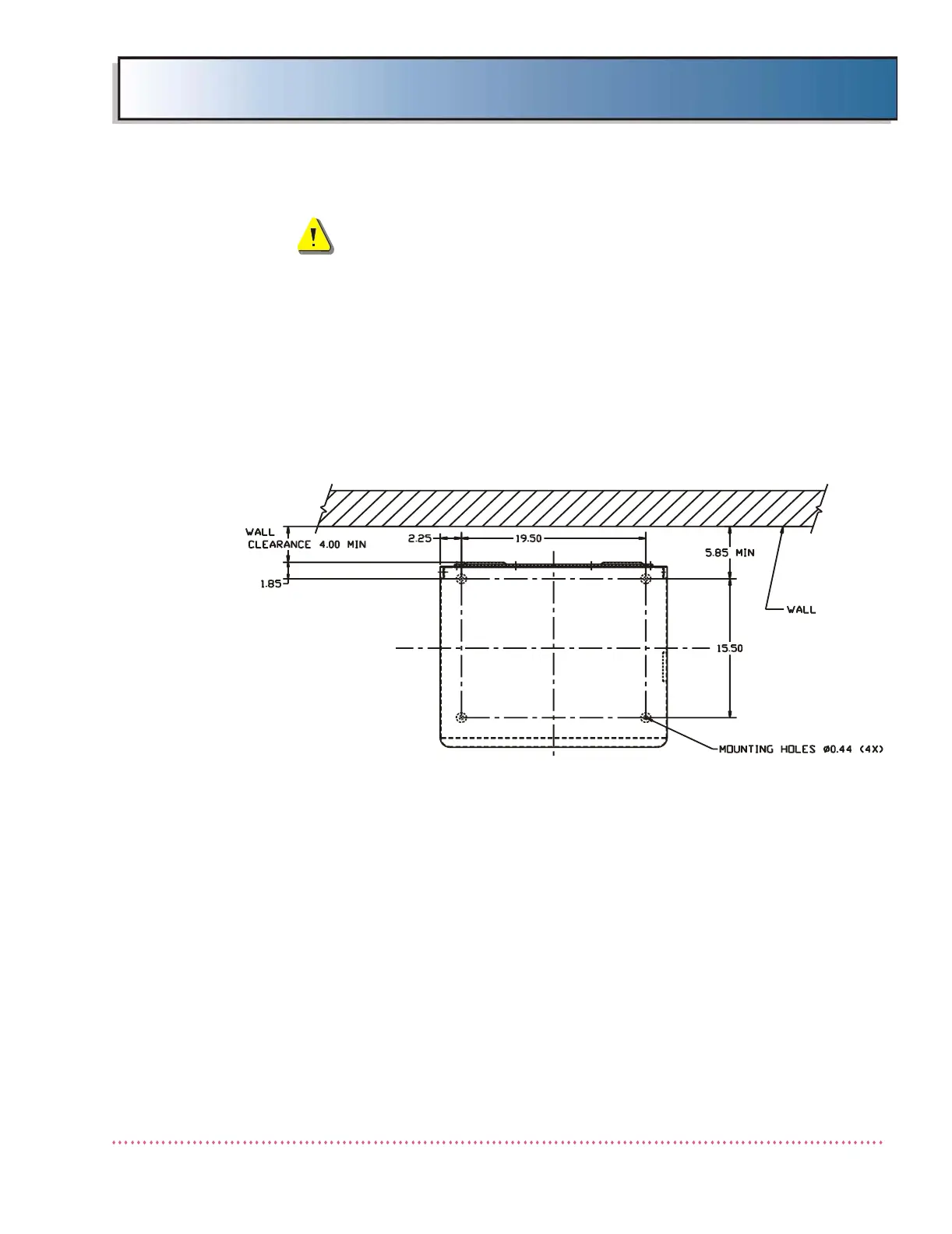
3. If mounting generator to floor, mark locations of the four mounting holes on
floor in accordance with dimensions given in Figure 2-2. Drill four holes using
proper diameter drill bit (depending on mounting hardware used).
Figure 2-2. Generator Cabinet Mounting Hole Locations
4. Position the generator chassis in its mounting location and place a level on
flat horizontal surface of chassis. If chassis is not level, add shim(s) below
generator as required until level.
5. After all cable connections that require access to the rear of the generator are
complete, secure cabinet to floor using 3/8" diameter mounting hardware
suitable for floor construction type.
 Loading...