Chapter 2 Assembly & Installation
Revision W HF Series X-ray Generators - Service Manual
2-42 Quantum Medical Imaging
8. Connect the yellow/green ground wires at each end of OCP serial cable to
the nearest mounting screw on OCP Control Board A16A1 (AY40-004S)
and Logic Board A1 (AY40-006S).
9. Ensure the connector screws and PCB mounting screws are fully tight-
ened.
CAUTION! The OCP serial cable shield is electri-
cally connected to the connector shells at either
end of the cable. It is recommended the OCP
serial cable connectors not be removed so as not
to compromise integrity of cable shield connec-
tions. If necessary to remove connector, verify
that after the connectors are re-installed, there is
less than 0.1 ohm resistance between connector
shell at one end of cable and the connector shell
at opposite end of the cable.
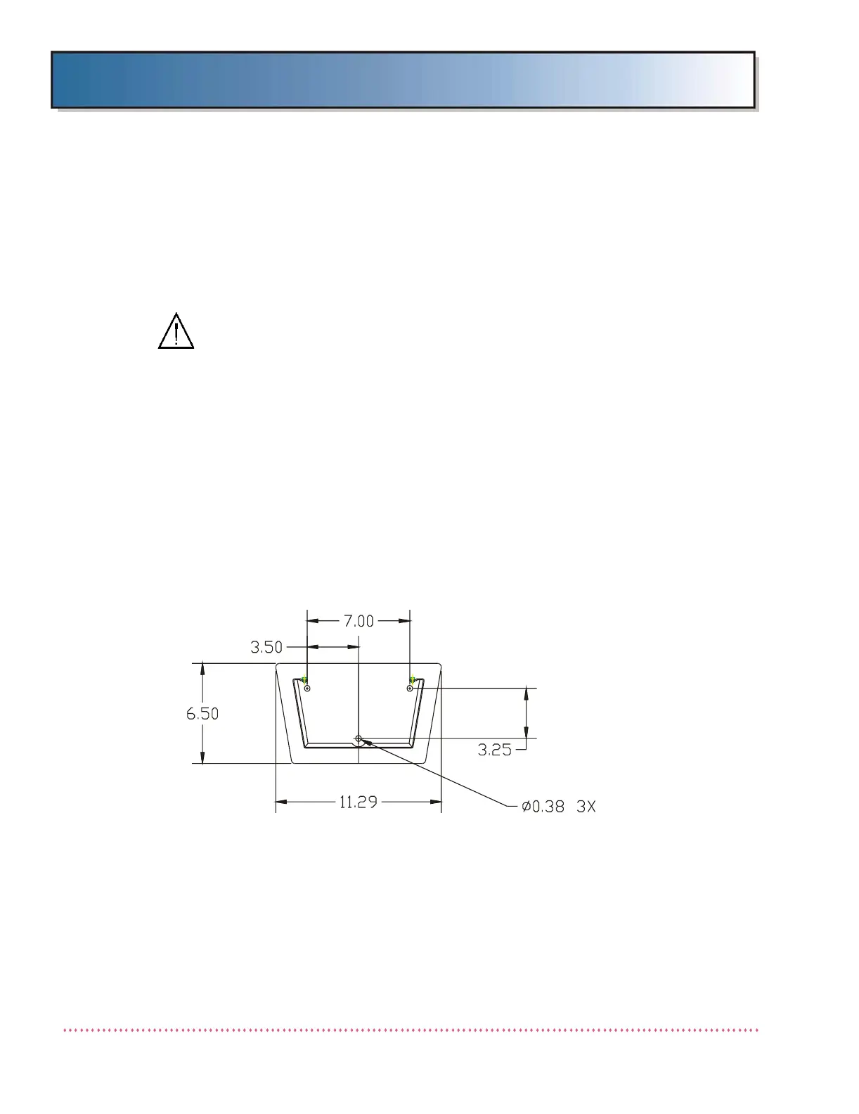
10. If mounting OCP to floor, either transfer drill four mounting holes in floor
using the OCP base plate as a guide or mark the floor in accordance with
dimensions given in Figure 2-23, and then drill holes where marked. Drill
holes using a #W drill bit (0.390" diameter). After OCP cable connection
is complete, secure OCP to floor using 3/8" hardware suitable for floor
type.
Figure 2-23. OCP Mounting Hole Locations
 Loading...