EasyManuals Logo

RADIOMETER ABL 77 Series User Manual

RADIOMETER ABL 77 Series
355 pages
To Next Page IconTo Next Page
To Previous Page IconTo Previous Page
Page #104 background imageLoading...
Page #104 background image
Chapter 4: Test and Calibration Procedures ABL77 Service Manual
Check Valve Fluidics System, Continued
Test procedure
diagrams
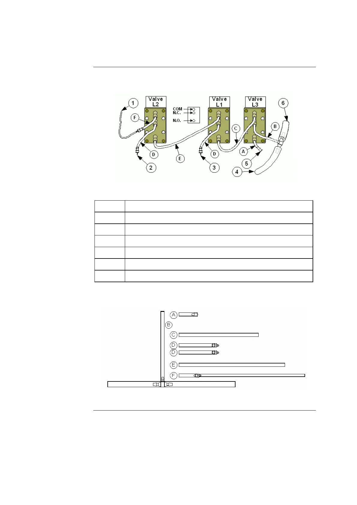
The following diagrams should be used for reference when testing the check valve
fluidics system. Figure 4-5 shows the fluidics connections.
Figure 4-5
Part Function
1. To sensor cassette fitting luer
2. To CAL1 luer
3. To Cal2 luer
4. To printer chassis
5. Plug
6. To waste drain
Figure 4-6 identifies the different pieces of tubing used in the check valve fluidics
system.
Figure 4-6
Figure 4-6Continued on next page
4-16 Rev. F

Table of Contents

Questions and Answers:

Question and Answer IconNeed help?

Do you have a question about the RADIOMETER ABL 77 Series and is the answer not in the manual?

RADIOMETER ABL 77 Series Specifications

General IconGeneral
BrandRADIOMETER
ModelABL 77 Series
CategoryMeasuring Instruments
LanguageEnglish

Related product manuals