ABL77 Service Manual Chapter 6: Replacements
Main Analog Cable
Introduction
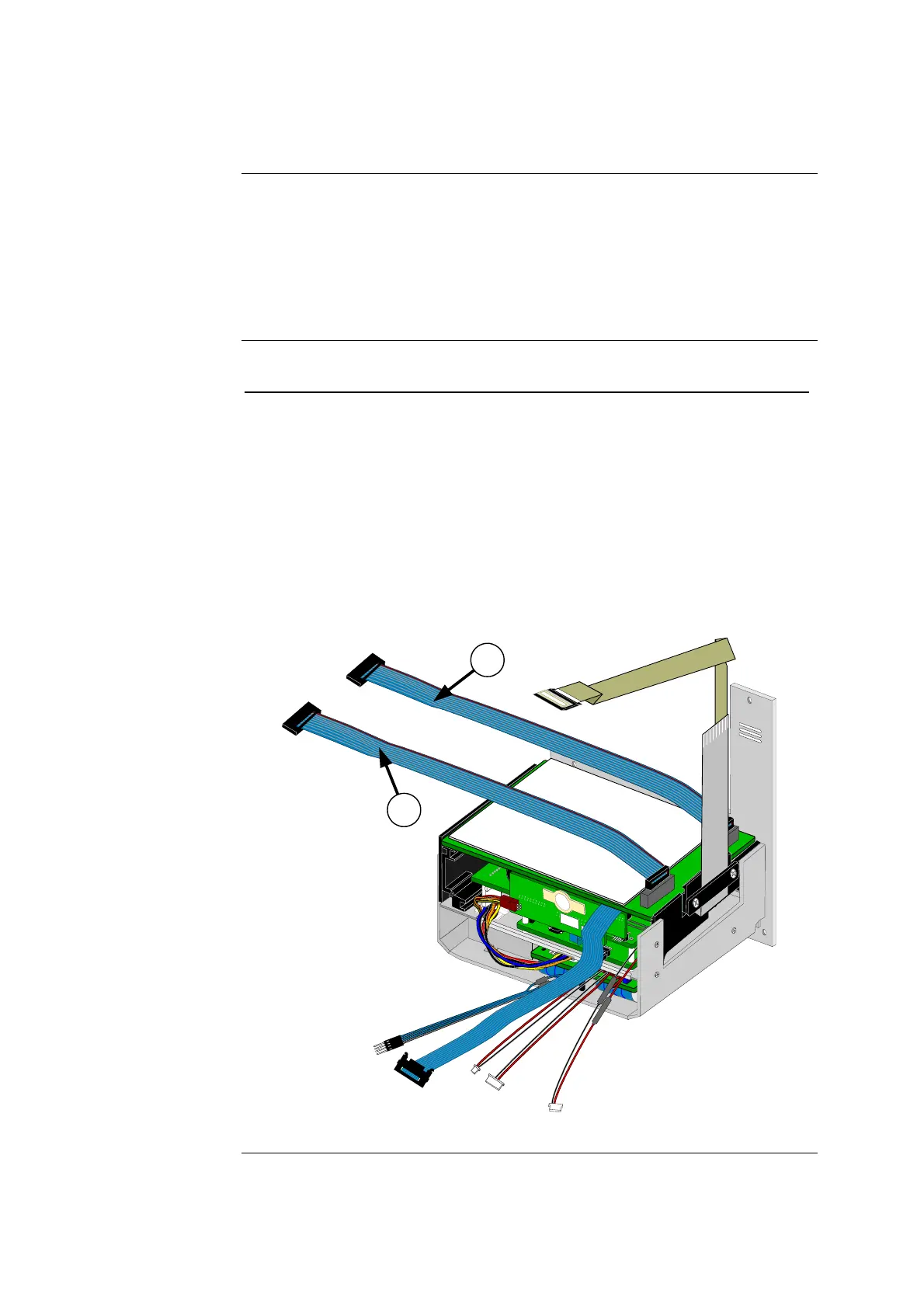
The main analog cable (REF: 636-440) is used in two locations that serve different
functions.
One cable is the input/output cable (I/O Cable) for data between the analog board
and the valve board. The other cable is the Sensor Cable, which transfers data from
the sensor cassette to the analog board.
Follow these steps to replace either or both main analog cables.
Step Action
1.
Remove the electronics module. One end of the main analog cable
will be disconnected when the lower module is removed.
2.
Disconnect the old main analog cable(s) from the analog board.
3. Connect the new main analog cable(s) to the analog board (item 1
and/or 2 in figure 6-26).
NOTE: This cable is keyed for proper orientation. Both ends of the
cable have identical wiring connections, so either end can be
installed.
4.
Re-assemble the analyzer starting with the electronics module.
A
S
S
Y
4
0
9
3
3
1
2
Figure 6-26
Rev. F 6-43

 Loading...