EasyManuals Logo

RADIOMETER ABL 77 Series User Manual

RADIOMETER ABL 77 Series
355 pages
To Next Page IconTo Next Page
To Previous Page IconTo Previous Page
Page #282 background imageLoading...
Page #282 background image
ABL77 Service Manual Chapter 7: Re-Assembly
Opto-Sensor
Introduction
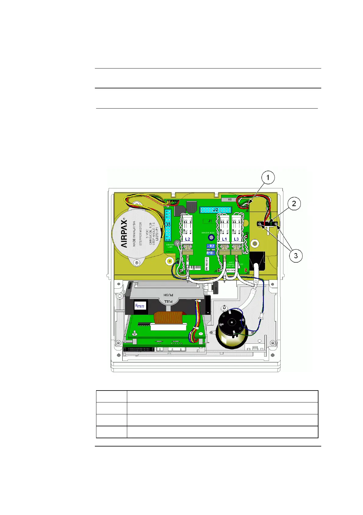
Follow these steps to re-attach the opto-sensor cable as shown in Figure 7-19.
Step Action
1.
From the back of the module, place the opto sensor into the
rectangular opening in the upper right of the housing.
2.
Fasten the sensor in place with four nylon washer and two Phillips
head screws.
3.
Connect the cable to J6 of the valve board with the green wire in the
top position, as shown below.
Figure 7-19
Part Function
1. Opto-sensor cable connection – J6, green wire on top
2. Opto-sensor with cable
3. Opto-sensor nylon washers and screws
Rev. F 7-31

Table of Contents

Questions and Answers:

Question and Answer IconNeed help?

Do you have a question about the RADIOMETER ABL 77 Series and is the answer not in the manual?

RADIOMETER ABL 77 Series Specifications

General IconGeneral
BrandRADIOMETER
ModelABL 77 Series
CategoryMeasuring Instruments
LanguageEnglish

Related product manuals