Chapter 5: Dismantling ABL77 Service Manual
Electronic Boards Assembly
Introduction
This section describes the process for replacing the LCD adapter board, memory
module, ChipDisk board, CPU and touch screen controller boards.
NOTE: When the CPU is disconnected from the coin cell battery on the interface
board, the CPU CMOS will lose its settings and must be re-programmed. See the
instructions for re-programming the CPU CMOS settings in Chapter 4, Test and
Calibration Procedures.
NOTE:
Electronics
boards assembly
diagram
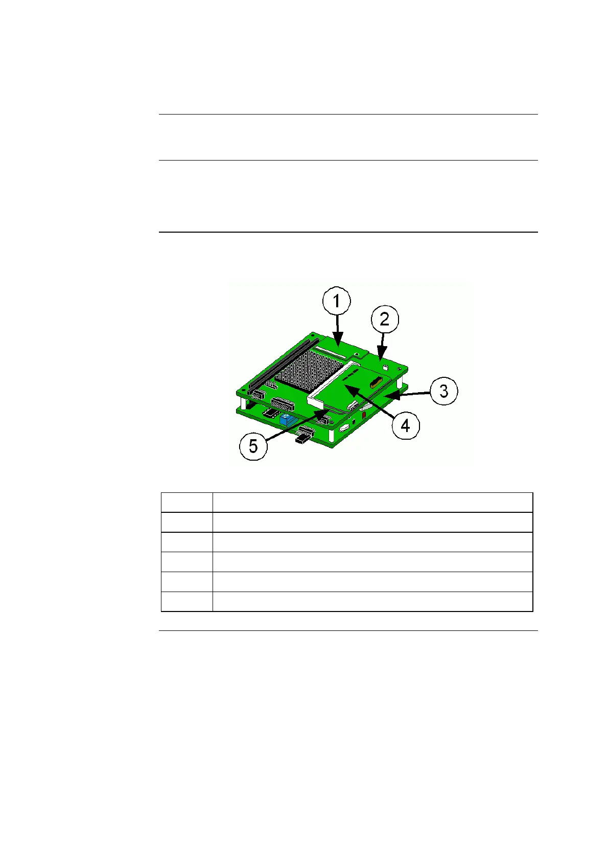
This diagram will be used throughout this section to identify the appropriate
boards.
Figure 5-28
Part Function
1. ChipDisk
2. CPU board
3. Touch screen board
4. LCD adapter board
5. Memory module
Continued on next page
5-44 Rev. F

 Loading...