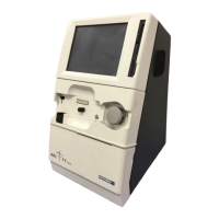
ABL77 Service Manual Chapter 6: Replacements
Cabling
Introduction
The ABL77 internal cabling connects between the various modules and boards.
At least one end of each cable is connected in the electronics module and to
remove the electronics module requires disconnecting the upper and lower
modules. For this reason, all instructions start with removing the electronics
module.
The following cables connect the upper module to the electronics module.
636-444 Disk drive cable
636-447 LCD display cable
636-439 Backlight inverter cable
636-441 Touch screen cable
The following main analog cables (636-440) connect the lower module to the
electronics module.
• I/O cable
• Sensor cable
There are no cables that directly connect the upper module to the lower module.
The following cables are connected within the electronics module.
636-487 Analog power cable
636-488 Power board cable
636-442 A/D cable – analog board to CPU board
636-443 Printer data cable
636-435 Printer power cable
636-442 A/D cable – analog board to battery control board
636-445 COM1 cable
636-438 Ethernet cable
636-437 Power switch cable
636-436 Bar code gun / keyboard cable
Continued on next page
Rev. F 6-33

 Loading...