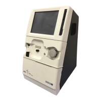
ABL77 Service Manual Chapter 4: Test and Calibration Procedures
5 Volt Power Output Setting
Introduction
This topic describes how to verify and, if necessary, adjust the 5 volt power output
supply from the Battery Control Board.
Equipment
required
• Valve Board Calibration Cassette, REF: 920-729
• Small flat head screwdriver for adjusting the calibration settings
• Digital multimeter or voltmeter
Verify 5 volts
Follow these steps to verify the 5 volt output.
Step Action
1.
Power down the analyzer and disconnect from AC power source.
Remove any sensor cassette.
2.
Slide out the printer module; DO NOT disconnect the cables.
3.
Connect the leads of the digital voltmeter to the back-side leads of the
2-pin power cable where it attaches to the printer module.
4.
Plug the battery charger into the rear panel and plug the power cord
into AC power.
5.
Turn the electronics module power switch on. Wait for the Main
Menu to appear on screen.
6.
Verify that the voltmeter reading is 5.20 ±0.02 VDC.
7.
If the voltage falls within the acceptable range of 5.20 ±0.02 VDC, the
5 volt supply is properly calibrated.
8.
If the voltage does not fall within the acceptable range, proceed to
“Calibrate 5 volts” to adjust the voltage.
Continued on next page
Rev. F 4-29

 Loading...