Chapter 6: Replacements ABL77 Service Manual
Valve Board, Continued
Valve Board
Diagrams
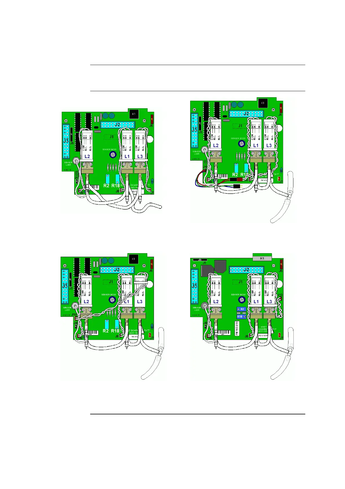
These figures show the possible wiring connections for valve L3, depending on the
valve board and the fluidics system installed in the analyzer.
Figure 6-2 — Valve board with replaceable
valves and original fluidics.
Figure 6-3 — Valve board with replaceable
valves and check valve fluidics using the
Y-cable for L3.
Figure 6-4 — Valve board with replaceable
valves and check valve fluidics using the J10
connector.
Figure 6-5 — Surface-mount design valve board
with check valve fluidics.
Continued on next page
6-12 Rev. F

 Loading...