Chapter 6: Replacements ABL77 Service Manual
Valve Board, Continued
Valve board
diagrams
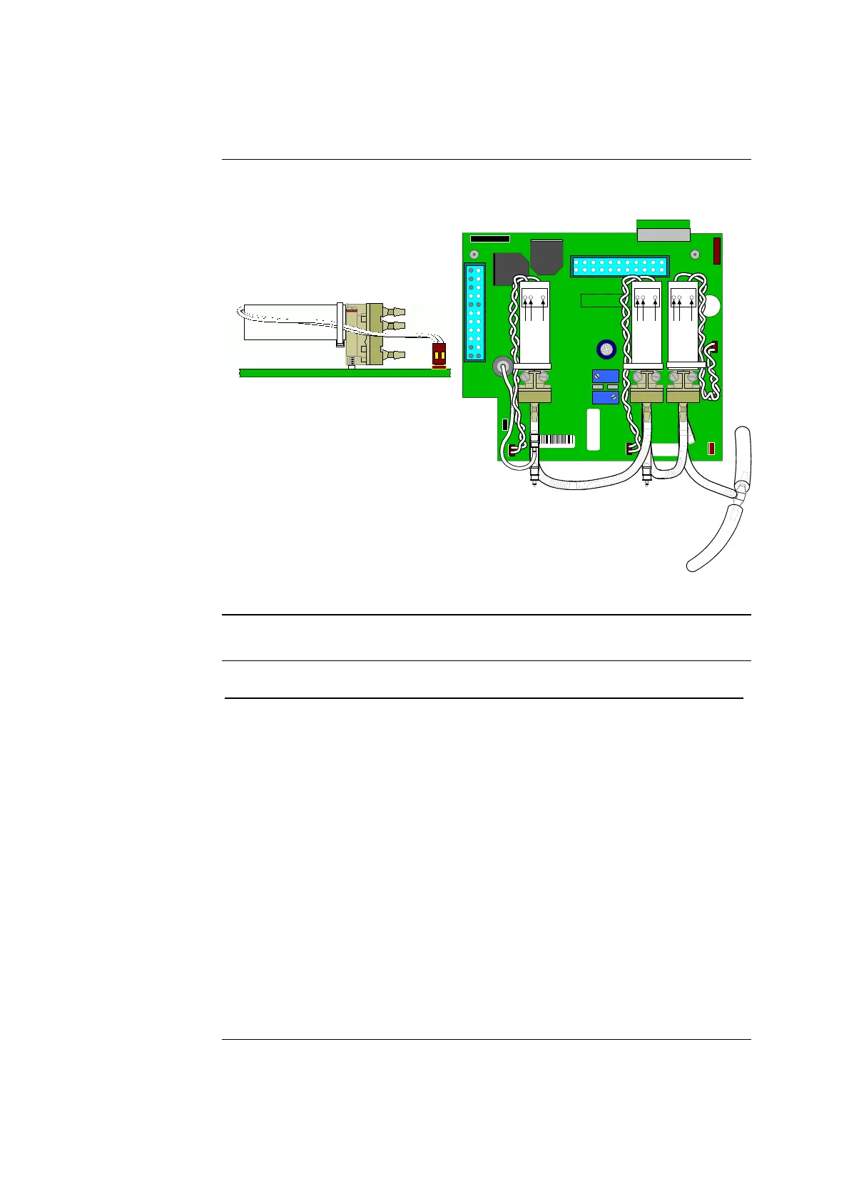
Figures 6-5 and 6-6 are included to illustrate the proper orientation when installing
valves.
Figure 6-6
41449 / B
41477
SERVICE BOARD ABL70-77
ASSY REV :
K1
J5
R2
R18
REVISION
J10
PN 902-811
J1
J9
SENSOR BOSS
SENSOR
LUER
J6
J4
J8
J7
J3
12 1
13 24
J2
2587
J6
J5
J4
J9
J8
J7
L2 L1 L3
J10
L3
COM
N.C.
N.O.
L1
COM
N.C.
N.O.
L2
COM
N.C.
N.O.
Figure 6-7
Installing the
new valve board
Follow these steps to install the new valve board only.
Step Action
1.
Place the new valves in the proper positions (see figures 6-5 and 6-6
for placement and orientation) on the new valve board and attach with
the two lock washers and two screws each.
2.
Tighten the screws down until they are close fitting, then turn each
screw an additional 1/2 turn to secure. Do not tighten more than 3/4 of
a turn as this may damage the valve.
3.
Connect the valve cables as appropriate.
• Valve L1 cable to J8
• Valve L2 cable to J9
• Valve L3 cable to J10
4.
Install new tubing according to the instructions in this chapter, under
Replacing the Valve Board Tubing.
5.
Insert the new valve board into the housing, aligning the sensor
connector with the front of the housing.
Continued on next page
6-14 Rev. F

 Loading...