ABL77 Service Manual Chapter 6: Replacements
Single Valve, Continued
Removing the
old valve
(continued)
Step Action
5.
Disconnect the cable of the malfunctioning valve from the valve board
connector; J7, J8, J9, J10 or the valve L3 Y-cable (Y-cable) on J4.
6.
Unscrew the two screws securing the malfunctioning valve to the
valve board. Lift the valve from the valve board and package properly
for return to SenDx for investigation.
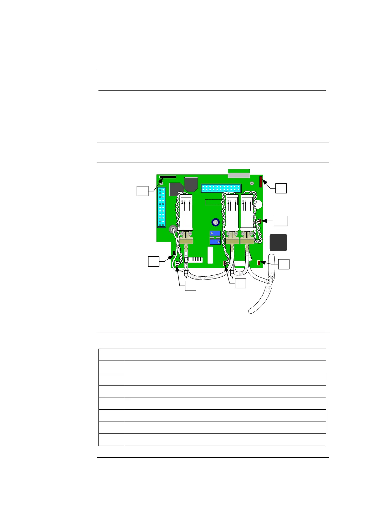
Valve board
diagram
Figure 6-10 shows the wiring connections of the current design valve board.
41449 / B
41477
SERVICE BOARD ABL70-77
ASSY REV :
K1
J5
R2
R18
REVISION
J10
PN 902-811
J1
J9
SENSOR BOSS
SENSOR
LUER
J6
J4
J8
J7
J3
12 1
13 24
J2
2587
J6
J5
J4
J9
J8
J7
L2 L1 L3
J10
L3
COM
N.C.
N.O.
L1
COM
N.C.
N.O.
L2
COM
N.C.
N.O.
J5
↑
J4
J6
J7
J8
J9
J10
Figure 6-10
Items and
descriptions
The following table describes the cable connections in figure 6-10.
Item Function
J4 Waste pump cable connection
J5 Roller pump cable connection
J6 Opto-sensor cable connection
J7 Former valve L3 connection
J8 Valve L1 connection
J9 Valve L2 connection
J10 New valve L3 connection
Continued on next page
Rev. F 6-19

 Loading...