ABL77 Service Manual Chapter 6: Replacements
Single Valve, Continued
Valve board
diagram
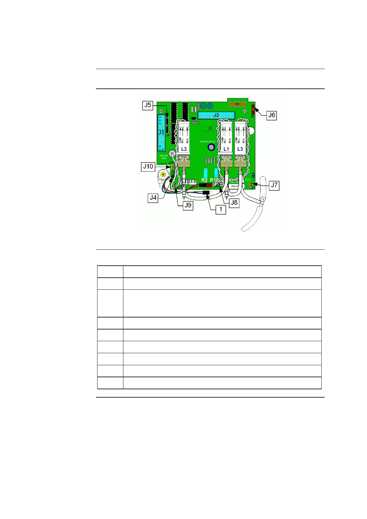
Figure 6-13 shows the wiring connections of the valve board using a Y-cable.
Figure 6-13
Items and
descriptions
The following table describes the cable connections in figure 6-13.
Item Function
1 Y-cable for valve L3
J4 Waste pump cable connection. This connection is used to connect the
Y-cable, which allows both the waste pump cable and valve L3 to
connect to this same location.
J5 Roller pump cable connection
J6 Opto-sensor cable connection
J7 Former valve L3 connection
J8 Valve L1 connection
J9 Valve L2 connection
J10 New valve L3 connection
Rev. F 6-21

 Loading...