ABL77 Service Manual Chapter 6: Replacements
Manifold, Continued
Installing the
new manifold
Follow these instructions to install a new manifold.
Step Action
1.
Connect the Cal1 port tubing from the new manifold to the adapter
connected to the N.C. valve port of L1. Make certain the tubing is
completely installed.
2.
Connect the Cal2 port tubing from the new manifold to the adapter
connected to the N.C. valve port of L2. Make certain the tubing is
completely installed.
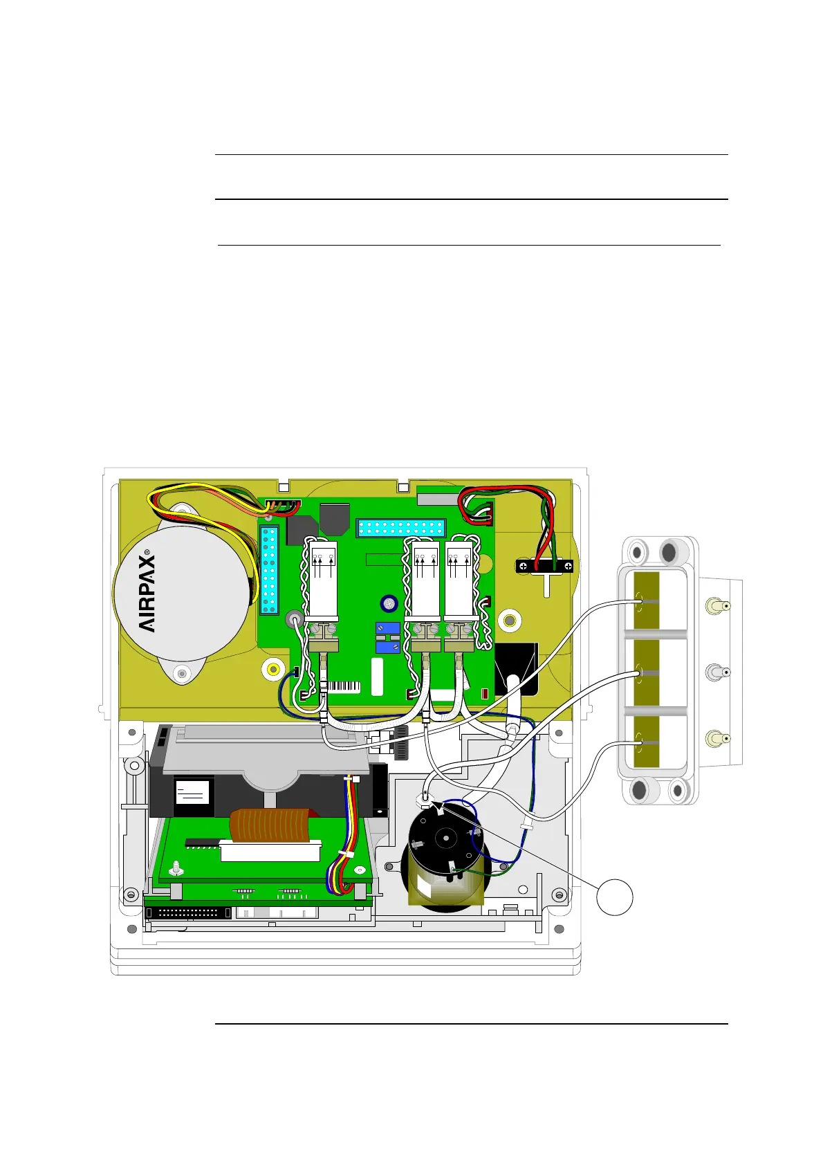
3.
Connect the new manifold waste tubing to the bulkhead connector
(item 1 in figure 6-17) on the printer chassis.
4.
Make certain that all of the cables and tubing are not pinched.
41449 / B
41477
SERVICE BOARD ABL70-77
ASSY REV :
K1
J5
R2
R18
REVISION
J10
PN 902-811
J1
J9
SENSOR BOSS
SENSOR
LUER
J6
J4
J8
J7
J3
12 1
13 24
J2
2587
J6
J5
J4
J9
J8
J7
L2 L1 L3
J10
Cal2 Waste Cal1
S H
LTP3345B-C576
A B C
PULL
PUSH
MADE IN MALAYSIA
STEPPER MOTOR
5: VDC
OHMS/COIL: 6.25
STEP ANGLE: 7.5
L82701-P1
L3
COM
N.C.
N.O.
L1
COM
N.C.
N.O.
L2
COM
N.C.
N.O.
1
Figure 6-17
Continued on next page
Rev. F 6-27
 Loading...
