Chapter 6: Replacements ABL77 Service Manual
Power Board Cable, Continued
Power board
cable
(continued)
Step Action
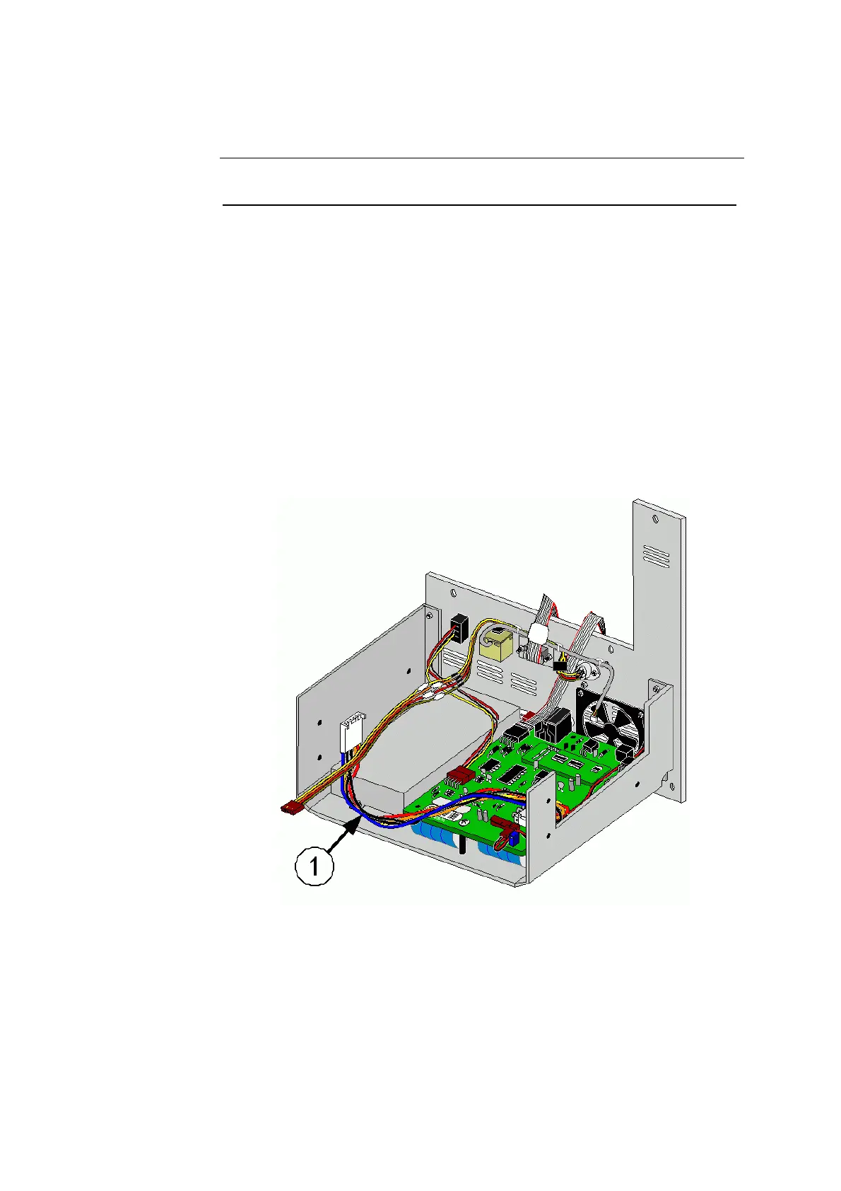
16. Connect the new power board cable (item 1 in figure 6-28) to J5 of the
power distribution board.
17.
Re-install the Ethernet cable (636-438) into the white connector in the
upper right corner of the CPU.
18.
Re-install the COM1 cable (636-445) into the connector on the front
right of the CPU with the red strip on the right. Pull excess cable out
between the interface board and the cable connector so the cable lays
flat on the CPU.
19.
Ensure all cables lie flat on top of the CPU.
20.
Re-install the analog board into the electronics module.
21.
Verify that the cable routing does not interfere with the components
on the analog board.
22.
Re-assembly the analyzer starting with the electronics module.
Figure 6-28
6-46 Rev. F