ABL77 Service Manual Chapter 6: Replacements
Barcode Reader / Keyboard Cable, Continued
Introduction
(continued)
Step Action
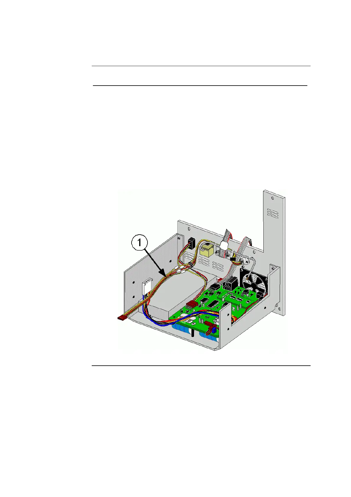
8. Install the new barcode reader / keyboard cable (item 1 in figure 6-35)
into the round opening above the fan with the alignment notch facing
up. Secure using two ¼” button head screws.
NOTE: If the connector does not have threaded inserts, fasten the
screws with two 4-40 hex nuts and two #4 internal star washers.
9.
Apply a small drop of Loctite 222 to the threads.
10.
Route the barcode reader / keyboard cable through the center and left
cable clamps on the rear panel then through the left two cable clamps
on the electronics shelf.
11.
Connect the barcode reader / keyboard cable to the interface board.
12.
Re-assemble the analyzer.
Figure 6-35
Rev. F 6-55
 Loading...
