ABL77 Service Manual Chapter 7: Re-Assembly
Valve Board Assembly, Continued
NOTE: Do not pre-stretch the tubing when fitting, this may cause the connections
to leak or draw air. The adapters are intended to eliminate connection problems.
NOTE:
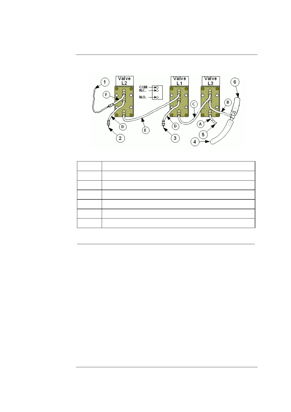
Figure 7-12
Part Connection
1 Sensor cassette fitting luer
2 Cal 1 adapter
3 Cal 2 adapter
4 Bulk head connector on the printer chassis
5 Plug – no connection
6 Waste drain
Step Action
4.
Attach the free tubing from the COM port of valve "L2" on the valve
board to the sensor cassette fitting luer.
5.
Attach one end of the free waste tubing attached from the N.C. port of
valve "L3" to the waste drain.
6.
Attach the other end of the free waste tubing attached from the N.C.
port of valve “L3” to the printer chassis port.
7.
Connect the Cal1 port tubing from the manifold to the adapter on the
tubing connected to the N.C. port of valve "L2".
8.
Connect the Cal2 port tubing from the manifold to the adapter on the
tubing connected to the N.C. port of valve "L1". The Cal1 and Cal2
port tubes will cross one over the other.
9.
Connect the manifold waste port tubing to the bulk head connector.
10.
Make certain all of the cables and tubing are not pinched.
11.
Test the tubing connections following the procedure in Chapter 4,
Testing the Valve Connections.
Rev. F 7-23

 Loading...