4-120 ECODRIVE03 DKC**.040, DKC**.100, DKC**.200 ECODRIVE03 Drive Controllers
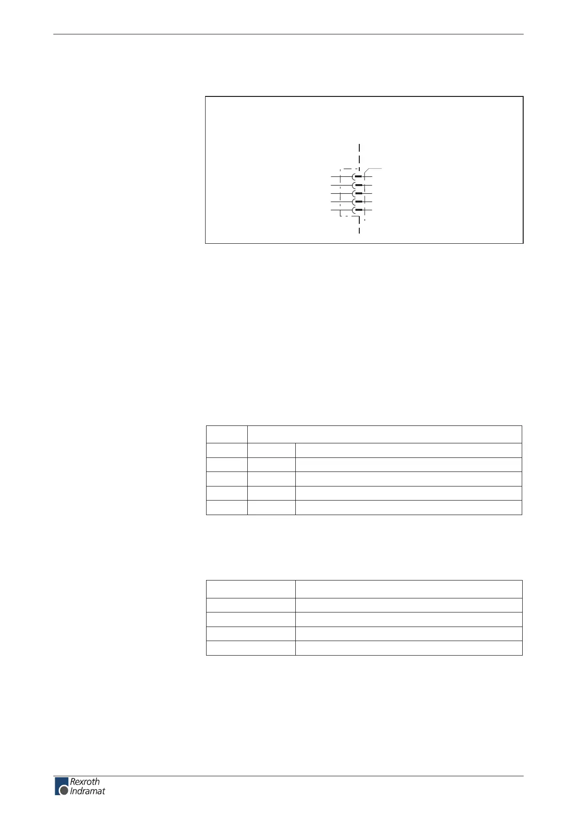
Connection diagram for DeviceNet-Interface
DKC06.3
AP5181F1.FH7
DeviceNet interface
X60
1
2
3
4
5
device-external device-internal
V-
CAN-
shield
CAN+
V+
Fig. 4-207: DeviceNet Interface for DKC06.3
as per DeviceNet Specication 2.0 Vol. 1
Open Screw Connector
as per DeviceNet Specication 2.0 Vol. 1, Appendix B
as per DeviceNet specication 2.0 Vol. 1, Appendix B
end resistance: 121 Ohm, 1%, ¼ W
as per DeviceNet specication 2.0 Vol. 1,
noitinifeDniP
V0-V1
langis laitnereffiD-NAC2
noitcennoc dleihSdleihs3
langis laitnereffiD+NAC4
ylppus ecafretnI+V5
Fig. 4-208: Interface signal allocation
+30 V
deef tnerruCegatlov suB
Am 07V 11
Am 54V 81
Am 53V 42
Am 82V 23
Fig. 4-209: Current feed via bus connector
The denition of the diagnostic displays is in the rmware function
description.
Connection
DeviceNet Interface:
Interface compatibility:
Recommended cable:
Bus participant connections:
Baud rate and cable length:
Plug-in connector assignment
X60:
Maximum bus voltage:
Current feed at bus:
Diagnostic display
H60 – H65:
customerservice@hyperdynesystems.com | (479) 422-0390
 Loading...

