Rexroth IndraDrive Arranging the Components in the Control Cabinet 7-23
DOK-INDRV*-SYSTEM*****-PR02-EN-P
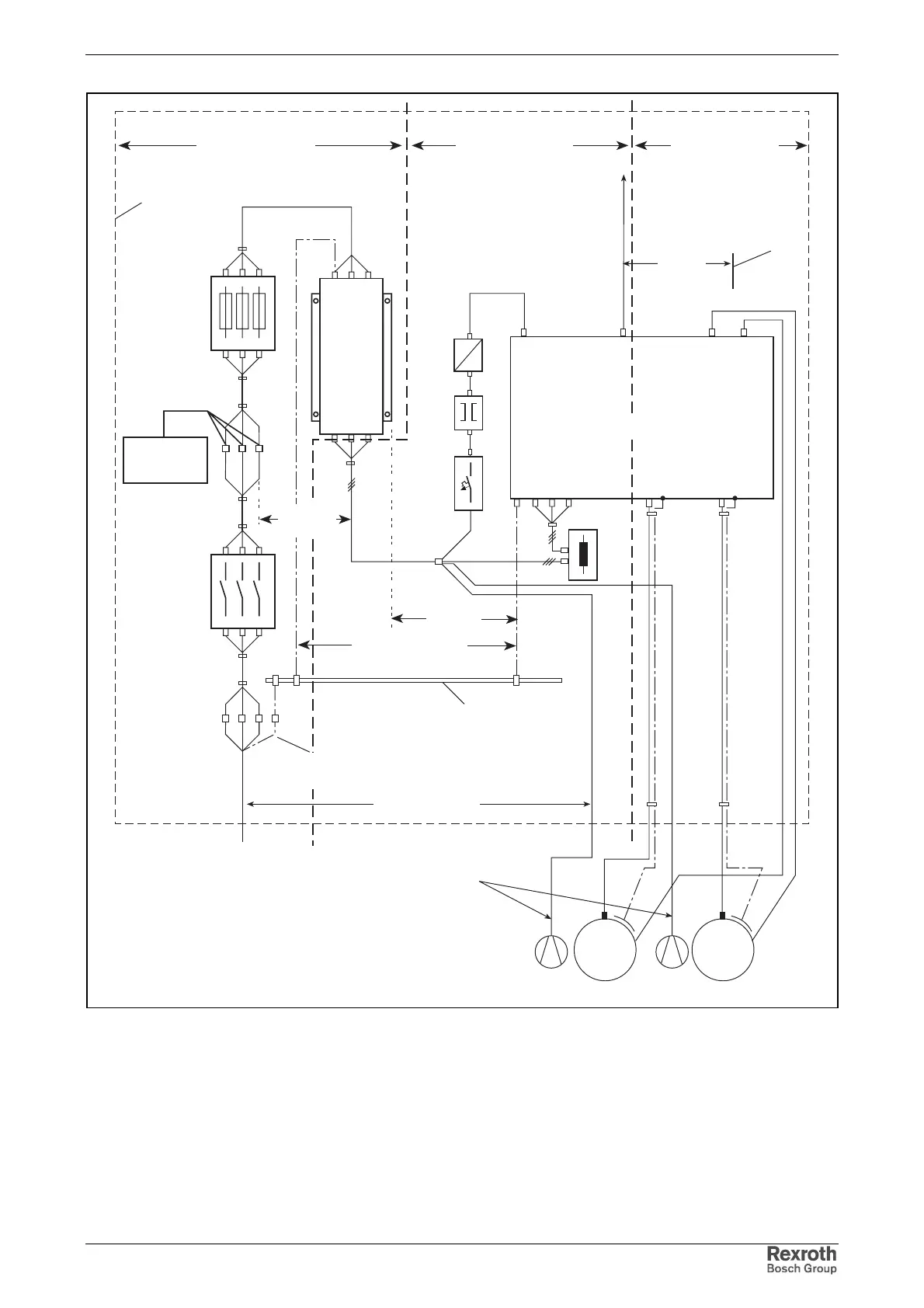
fuses
drives
distribution
other loads
of
installation
main switch
L1, L2, L3
PE
input
terminals
control cabinet
power supply cable
E1
E2
auxiliary or
control voltage
(single-phase or
three-phase)
motor encoder
connection
connection
motor
E3
M
3~
firmly connected
equipment grounding
conductor
area A area B area C
Z1
earth-circuit connector:
connect to mounting plate
over large surface area
DA000011v01_en.FH7
T
=
~
NT
Q2
LINE
mains filter
LOAD
connection
mains
control cabinet
Z1
Z2Z2
blower connection
single-phase or
three-phase
distance to
motor power
cable
M
3~
M
L
M
L
d3: min. 200 mm
d2: min.
500 mm
d4: min. 400 mm
d1: min.
200 mm
Q2: fusing
NT: power supply unit (if available)
T: transformer (if available)
DR1: mains choke (if available)
M
L:
motor blower (if available)
G: motor encoder connection
d5 =
min.
100 mm
DR1
connection
motor
signal lines
probes
reference cams
bus cables
drive system
Fig. 7-21: Separation of interference-free area and interference-susceptible
area in control cabinet