11-2 Control Circuits for the Mains Connection Rexroth IndraDrive
DOK-INDRV*-SYSTEM*****-PR02-EN-P
CAUTION
Danger of damage!
⇒
Make sure that the mains contactor opens, too, when
the Bb contact opens.
See Project Planning Manual for control section
⇒
See also Functional Description of firmware: "Power Supply"
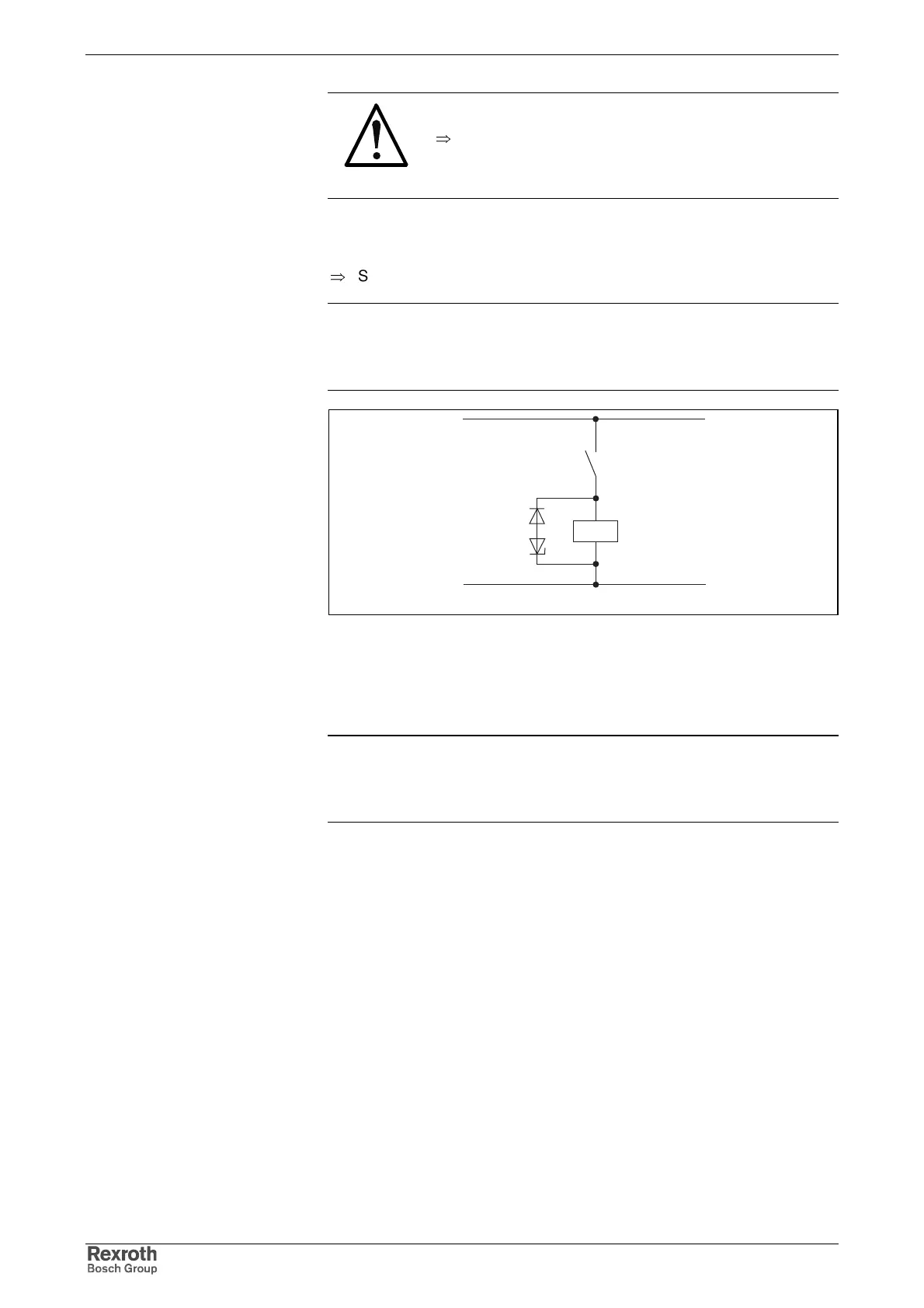
Note: When the internal line contactor is switched off, the contactor
coil causes overvoltages. These overvoltages may result in a
premature failure of the Bb contact. To attenuate overvoltages,
use overvoltage limiters with diode combination.
Bb_relais_schutz.FH7
K1
DC 24V
Bb
Fig. 11-1: Recommended suppressor circuit
Varistors and RC elements may not be used as suppressor circuit.
Varistors are subject to aging and increase their reverse currents. RC
elements overload the operating capacity of the Bb contact. This results in
premature failure of the connected components and devices.
Note: Comply with the load capability limits of the Bb contact.
Contactors with AC excitation and contactors exceeding the
load capability limits of the involved contact elements (Bb
contacts, etc.) should be controlled via contactor relays.
Switch States