11-6 Control Circuits for the Mains Connection Rexroth IndraDrive
DOK-INDRV*-SYSTEM*****-PR02-EN-P
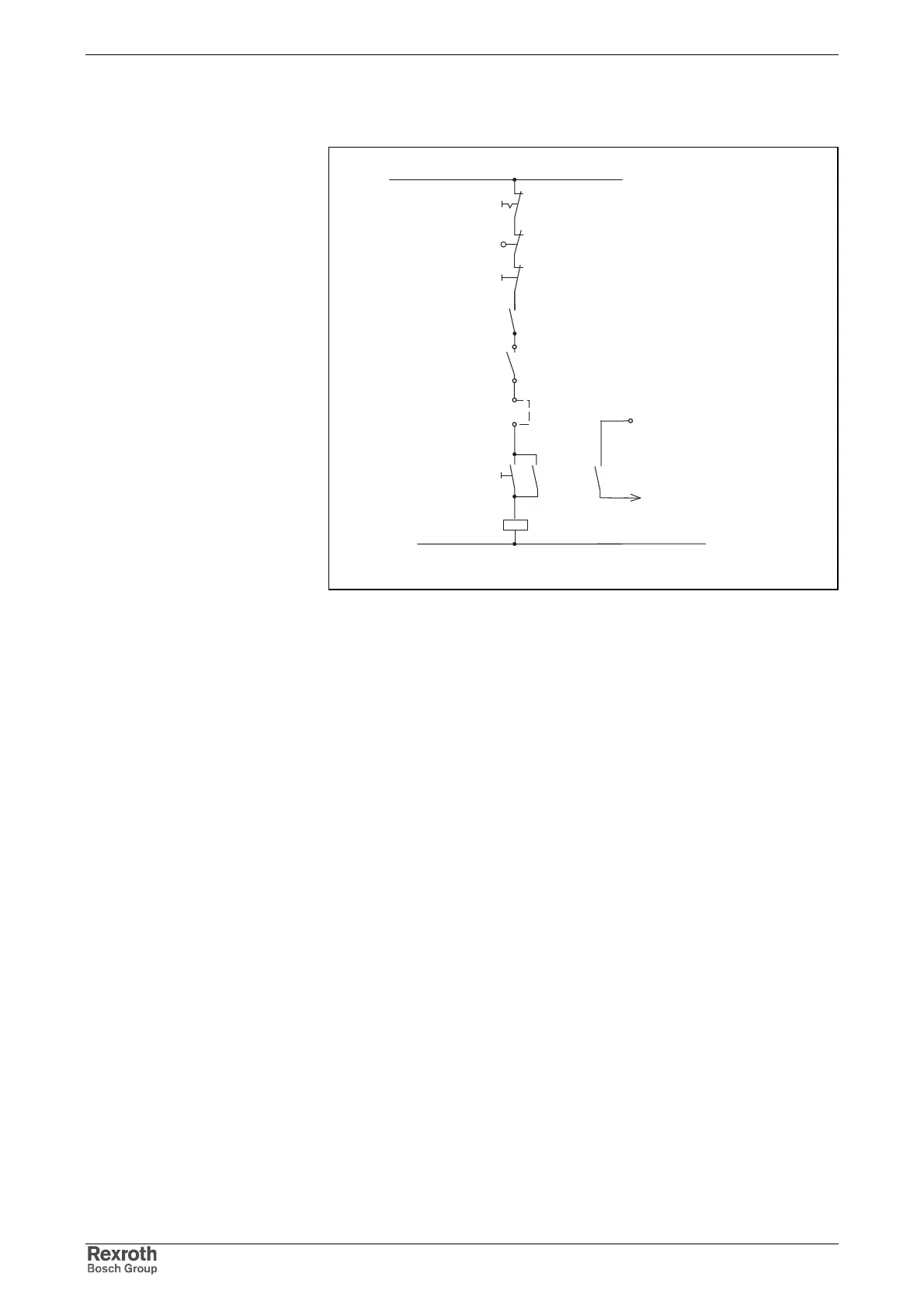
When the E-Stop pushbutton is actuated, the mains contactor drops out
which activates the DC bus short circuit device in the HLB.
steuersch_netzanschluss_hlb_c_mit_hcs02.fh
K1
Power on
Control unit error
message
Mains contactor
ext. control voltage
Bb
2)
1)
K1
Safety limit switch
Emergency stop
Power off
K1
HLB01.1C
X32.8
(DC bus short circuit\)
+DC24V
1) integrating the Bb contacts of other devices (see also Functional
Description of firmware: "Power Supply" and Parameter Description
of P-0-0300 and P-0-0861)
2) take switching capacity of Bb contact into account (Project Planning
Manual of control section)
Fig. 11-4: Wiring diagram HLB01.1 and HCS
Operating Principle