Rexroth IndraDrive Control Circuits for the Mains Connection 11-9
DOK-INDRV*-SYSTEM*****-PR02-EN-P
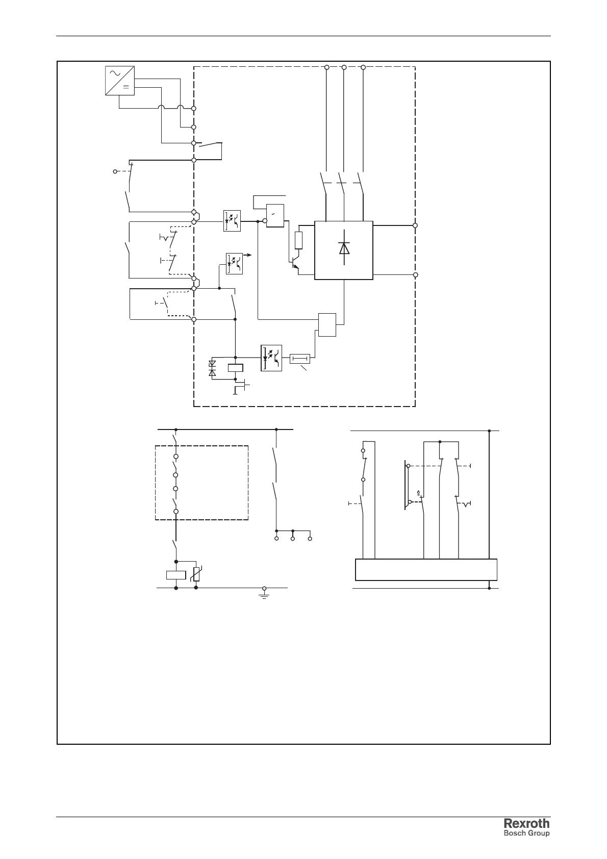
12
K4
K4
Drive
controllers
0V
U
Bb1
K1
ON delay
approx. 1.5 seconds ... 4 minutes 3)
&
enable
converter
K
DC bus
short circuit
Power supply unit
>1
A10
S1
S4
Control voltage
S11
S12
K1
Emergency-stop relay
A10
safety door
closed
Example. Depending on safety requirements at
the machine, additional monitoring devices and
locks may be necessary!
ready-to-
operate
K1
RF
Bb
UD
A10 = Emergency-stop relay
AF = drive enable of the drive controllers
Bb1 = power supply unit ready (drive system)
Bb = drive controllers ready
CNC = lag error message of control (use only contacts that do not open when E-stop switch is open)
K1 = mains contactor in power supply unit
K4 = drive enable signal control
RF = drive enable signal of the control unit
S1 = Emergency-stop
S2 = axis end position
S4 = power OFF
S5 = power ON
S11/S12 = safety door monitor
AF
AF
AF
S2
CNC
S5
K1
1)
1)
braking
resistor
control
2)
1) K1 control if no emergency-stop switch is used
2) unregulated rectifier in HMV01.1E; regulated one in HMV01.1R
3) depending on power supply unit and possibly connected external capacitors
A10
signal
processing
+24V
+/- 5%
HMV01.1E/
HMV01.1R
SS2HMV.fh7
24 V +/-5%
0 V
L+
L-
X32/9
X32/8
X32/7
X32/6
X32/5
X32/4
X31/5
X31/6
X33/4
X33/3
X31/4
X31/3
X33/1
X33/2
X3
X32/1
Fig. 11-5: Controlling the supply unit when electronic system of drive disturbed
with DC bus short circuit