15-6 Calculations Rexroth IndraDrive
DOK-INDRV*-SYSTEM*****-PR02-EN-P
Calculation to Reduce Generated Power Dissipation - Additional
External Capacitances at DC Bus
When the drive brakes, the rotary energy present in the mechanical
system is released as regenerative power in the DC bus of the drive
controller or combination of drive controllers. It can
• be converted into dissipation heat via the braking resistor integrated in
the drive controller or the additional braking resistor
- or -
•
be stored as energy in the drive controllers and possibly available
additional capacitors and reused for following acceleration processes.
This reduces the power dissipation generated in the control cabinet
and lowers the energy consumption.
The following applies to successful use of additional capacitors to avoid
unnecessary power dissipation in the control cabinet:
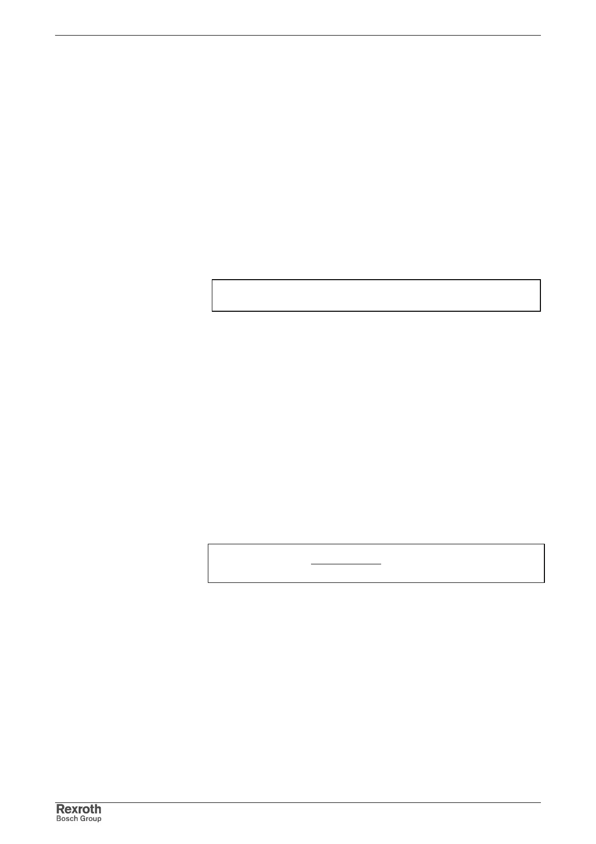
∑∑
≤ devicesZWWW ,oninstallatiR,
WR,installation: generated regenerative power of the installation
W
ZW,devices: storable energy of the DC bus capacitors
Fig. 15-17: Condition to avoid power dissipation from the regenerative power
Many acceleration and deceleration processes are typical for applications
with servo drives (e.g. nibbling machines or roll feeds). This is why it can
be useful for such applications to connect additional capacitors to the DC
bus of the drive controllers. This provides the following advantages:
• For drive controllers without mains regeneration function this prevents
the braking resistor in the drive controller from being switched on when
the drives brake: The dissipation heat in the control cabinet is
considerably reduced.
• The energy stored in the DC bus capacitors can be used for
acceleration. The energy demand of the drive is reduced.
The specific energy absorption capacity of the drive controllers can be
determined with the formula below.
()
22
__
*
)(
DCOnDCR
DCextDC
DC
UU
CC
W −
+
=
W
DC
: storable energy in DC bus
C
DC
: DC bus capacitance in device [F]
C
DCext
: external DC bus capacitance [F]
U
R_DC On
: braking resistor switch-on threshold
U
DC
: DC bus voltage
Fig. 15-18: Storable energy in DC bus
Additional Capacitors as Energy
Store
Storable Energy in DC Bus