15-8 Calculations Rexroth IndraDrive
DOK-INDRV*-SYSTEM*****-PR02-EN-P
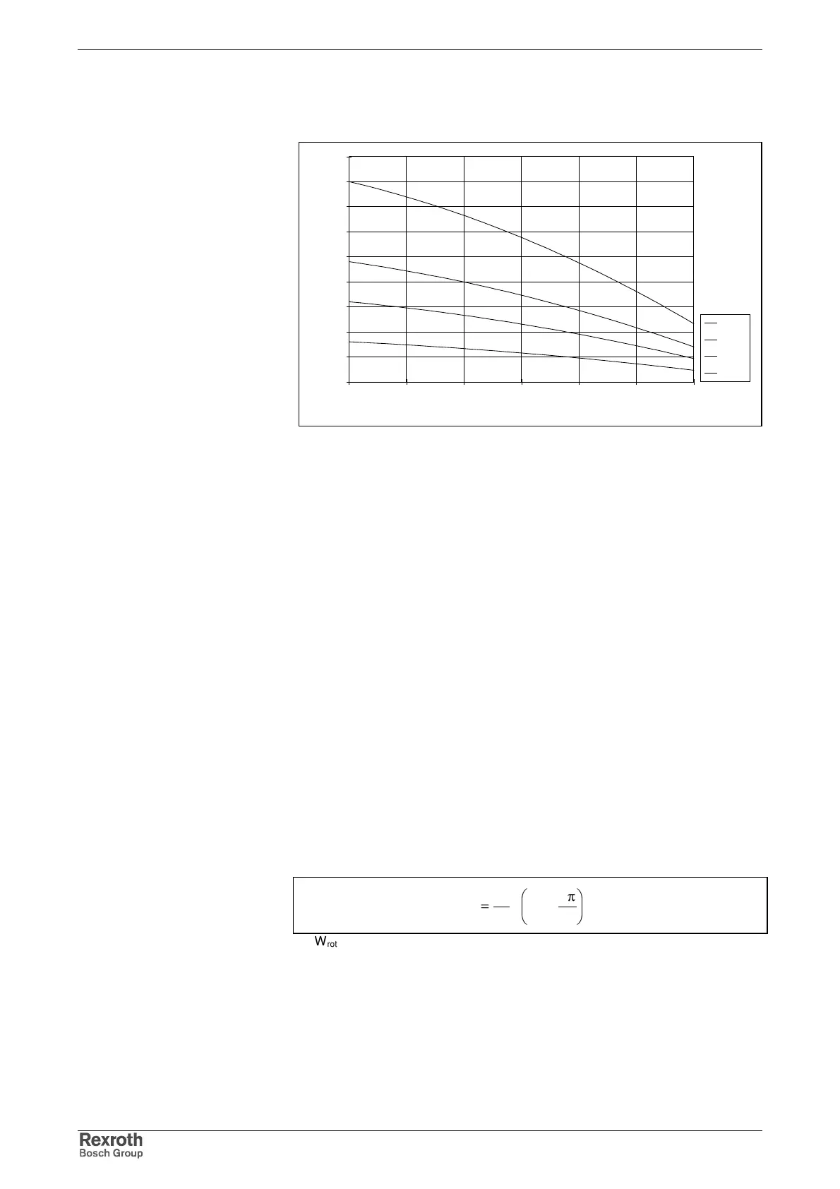
The figure below illustrates the characteristic of the storable energy in the
DC bus versus mains voltage with fixed switch-on threshold U
B
by the
example of HCS02.1E devices.
0
20
40
60
80
100
120
140
160
180
200 250 300 350 400 450 500
U
N1
[V]
W
ZW
[Ws]
W0070
W0054
W0028
W0012
Fig. 15-20: Storable energy in DC bus
Continuous Regenerative Power
In terms of average period of time, the sum of the continuous
regenerative power of all drives must not exceed the allowed continuous
power of the braking resistor(s).
In applications with servo drives at typical NC machine tools, machining
time is relatively long relative to the cycle time. Accordingly, the
continuous regenerative powers are only small. For this type of
applications, exact calculation is not required. It is sufficient to make sure
that the regenerative peak power is not exceeded.
Exact calculation is required, for example, for one of the following
applications:
Applications with servo drives which are characterized by many
acceleration and deceleration processes (e.g. nibbling machines or roll
feeds).
• Machine tools with modular main drive.
• Applications which involve lowering of large masses, e.g. loading
bridges, warehousing and transport systems.
Before the continuous regenerative power can be calculated, the rotary
energy of the drives and the potential energy of non-balanced masses
must be calculated.
z*
60
2
*n*
2
J
W
2
eil
g
rot
π
=
W
rot
: rotary energy [Ws]
n
eil
: speed at rapid traverse rate [min
-1
]
J
G
: inertia (motor + load) [kgm
2
]
z: number of braking processes per cycle
Fig. 15-21: Rotary energy of the drives