Rexroth IndraDrive Configuration of the Drive System Rexroth IndraDrive 6-7
DOK-INDRV*-SYSTEM*****-PR02-EN-P
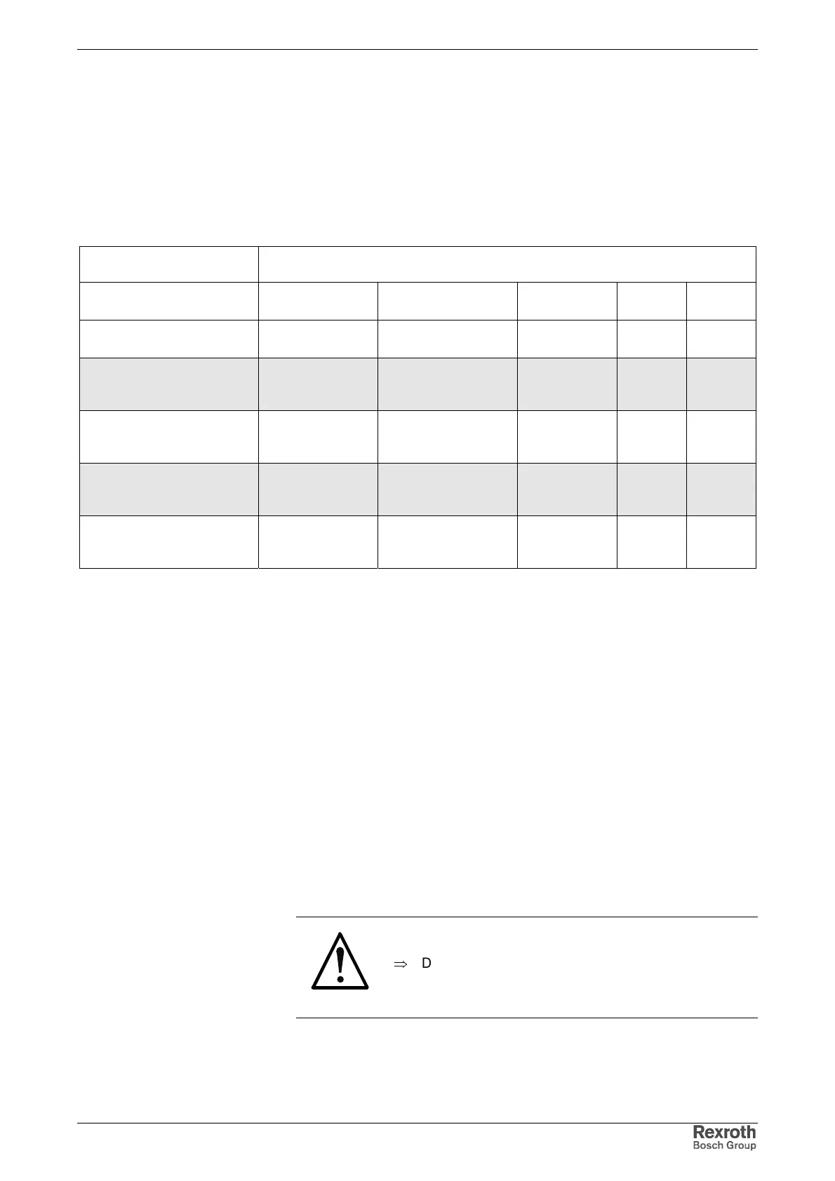
Central Supply HCS02 with HCS02
Up to the indicated maximum allowed number of axes, drive controllers
with braking resistor may be combined at the common DC bus according
to the table below. The number is limited by the ability of the supplying
HCS02 to charge Y-capacitors.
You may make replacements up to the maximum allowed sum of the type
currents.
Type of mains connect. (1)
Maximum number of IndraDrive C components at common DC bus (plus
supplying device in the case of central supply)
HCS02.1E
max. allowed sum of
type currents
max. allowed
number of axes
HLB01.1C HLC01.1C
central supply via
HCS02.1E-W0028
-- --
-- 1 1
central supply via
HCS02.1E-W0054 without
assigned mains choke
up to max. W0054 166 12 1 1
central supply via
HCS02.1E-W0054 with
assigned mains choke
up to max. W0054 222 12 1 1
central supply via
HCS02.1E-W0070 without
assigned mains choke
up to max. W0070 264 12 1 1
central supply via
HCS02.1E-W0070 with
assigned mains choke
up to max. W0070 402 12 1 1
--: not allowed
(1) for explanation see chapter
Fig. 6-8: Maximum number of IndraDrive C components at common DC bus
central supply via HCS02.1E-W0070 with assigned HNL01.1 mains
choke:
• 1 * HCS02.1E-W0070 (supplying device)
• 8 * HCS02.1E-W0028
• 2 * HCS02.1E-W0054
• 1 * HCS02.1E-W0070
• 1 * HLB01.1C
• 1 * HLC01.1C
sum of type currents (to be supplied): 402
sum of drive controllers with braking resistor: 12
sum of all IndraDrive C components: 14
CAUTION
Damage to the drive controller!
⇒
Do not exceed allowed peak and continuous powers
in the DC bus.
Example