7-4 Arranging the Components in the Control Cabinet Rexroth IndraDrive
DOK-INDRV*-SYSTEM*****-PR02-EN-P
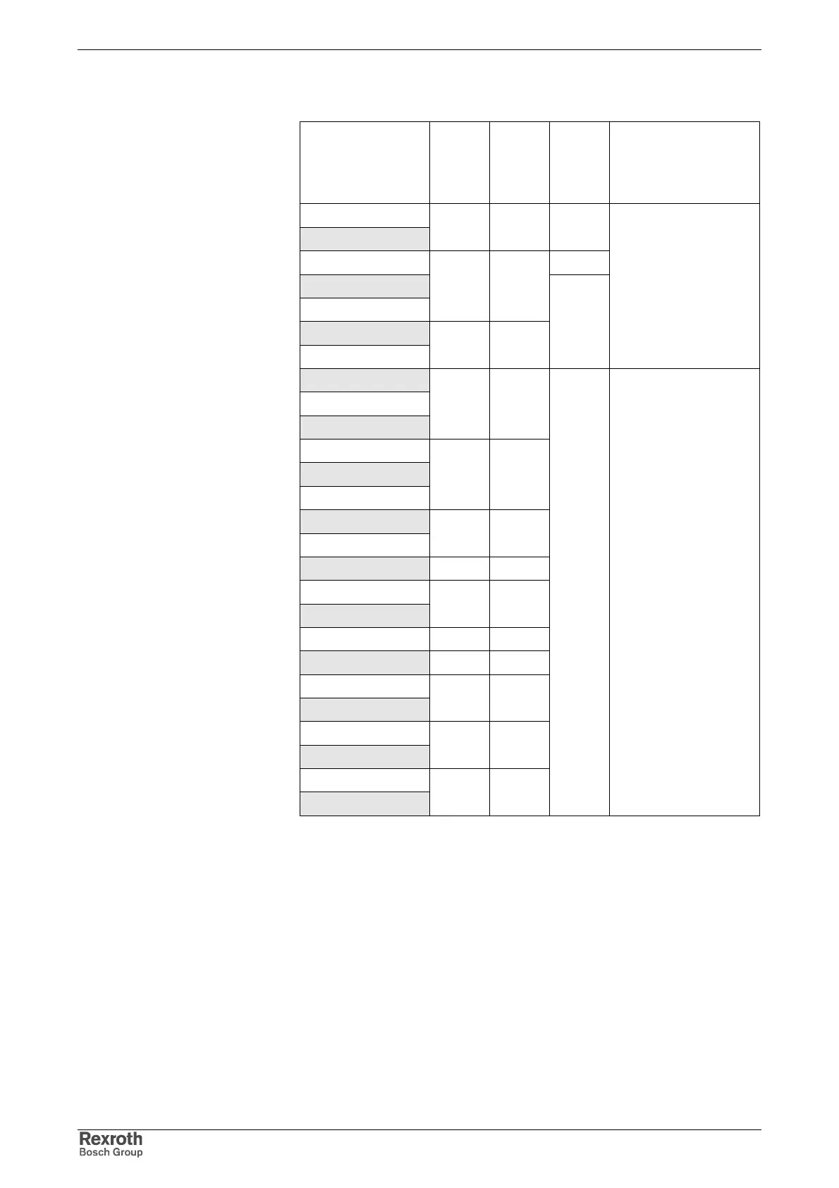
Device Depths, Heights and Widths
Device Device
width C
[mm]
Min.
moun-
ting
width
[mm] 1)
Device
height
[mm] 2)
Device depth
[mm] 3)
HLC01.1C-01M0
HLC01.1C-02M4
50 50 352
HCS02.1E-W0012 290
HCS02.1E-W0028
HLB01.1C
65 70
HCS02.1E-W0054
HCS02.1E-W0070
105 110
352
265
for control cabinets with
at least 300 mm of
depth
HMS01.1N-W0020
HMS01.1N-W0036
HMD01.1N-W0012
50 50
HMS01.1N-W0054
HMD01.1N-W0036
HLC01.1D-05M0
75 75
HMS01.1N-W00100
HLB01.1D
100 100
HCS03.1E-W0070 125 125
HMS01.1N-W0150
HMV01.1E-W0030
150 150
HMV01.1R-W0018 175 175
HMS01.1N-W0210 200 200
HCS03.1E-W0100
HCS03.1E-W0150
225 225
HMV01.1E-W0075
HMV01.1R-W0045
250 250
HCS03.1E-W0210
HMV01.1R-W0065
350 350
440
322
for control cabinets with
at least 400 mm of
depth
1) incl. minimum distance between the components
2) device body without mounting flange on top and bottom, as well as
minimum distances for ventilation and installation
3) incl. touch guard, connector housing, bending radius of fiber optic
cable
Fig. 7-4: Mounting dimensions in [mm]