Sirius 800 Series User Manual Sirius 840/850 Module Locations 8.3
Iss 5 Rev 7 Page 105 © 2017 SAM
The panel has three (DS-Link) output connectors (see note below) and connects to the
equivalent placed input connectors (a, b & c) that are at the bottom of the Output Rear Panel
of the second Sirius 850 frame.
The three expansion cables must be purchased separately, cable order codes are shown
below.
• 1 x 6 meter (19 Feet) expansion cable SAM order code: FGAEY WDS6THIN
• 1 x 12 meter (39 Feet) expansion cable SAM order code: FGAEY WDS12THICK
The DS-Link input connectors on the 1365 rear panel (d in, e in & f in) are used to expand a
Sirius 850 system above 1152
2
(future enhancement).
See section 12.2.212.8 for details of the DS-Link connections between the Sirius 850 frames.
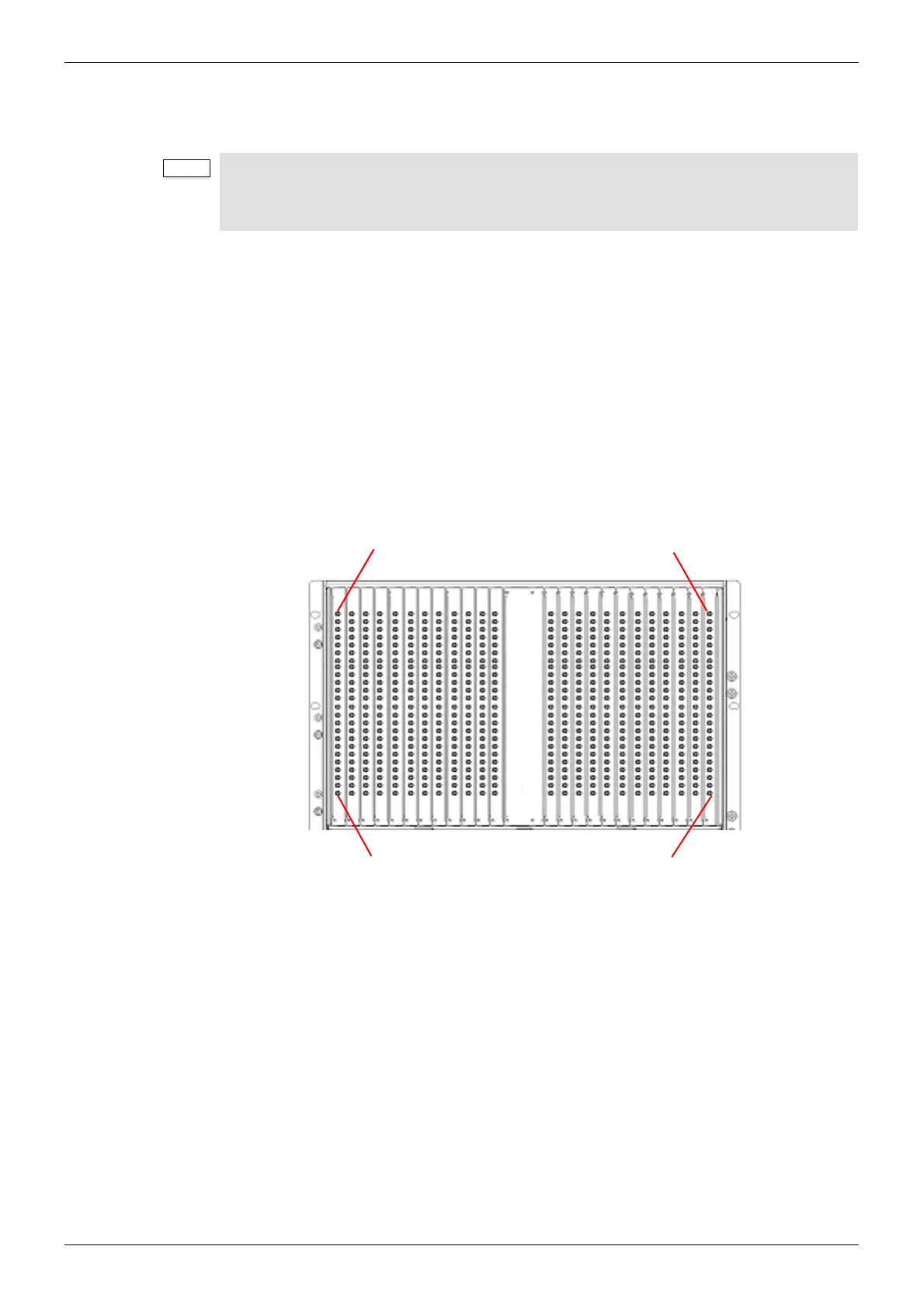
8.3.8.2 1366 Expansion Output Rear Panel Configuration
The output from the 5928 Expansion Output Module is via the 1366 24 Channel Expansion
Output Rear Panel.
The 1366 Expansion Output Rear panel has 24 x HD BNC connectors.
• 1290 Rear Panel - the DS-Link expansion output connectors are marked A, B & C
• 1365 Rear Panel - the DS-Link expansion output connectors are marked A OUT,
B OUT & C OUT
Figure 68 Sirius 850 Expansion 1366 Output Rear Panel Configuration