Sirius 800 Series User Manual Sirius 840/850: Alarm Rear Panel Connections Control and Alarm Rear Panel Connections 16.3
Iss 5 Rev 7 Page 297 © 2017 SAM
16.3.1 Sirius 840/850: Frame ID Rotary Switch on the Alarm Rear Panel
Each Sirius 840/850 router frame contains a rotary decimal switch situated on the Alarm rear
panel, it is used to identify the system being used.
The frame number is set using a 10 way rotary decimal switch on the rear of the router (see
Table 86). This uniquely identifies the Sirius 850 router within a multiple frame expanded
system.
The Frame ID switch should be set according to the following table:
Frame ID Rotary Switch - Frame identification switch
(see section 16.3.1 for full details):
Sirius 840 - set to position 3
Sirius 850, single frame - set to position 0
Sirius 850, frame 1 of 2 - set to position 1
Sirius 850 frame 2 of 2 - set to position 2
Door Ethernet RJ45 Ethernet - Used to connect the door PC to an external
network
Door Fuse &
Spare Fuse
5 A Anti-Surge, Ceramic fuse (5 mm x 20 mm)
Connector Function
Table 86 Sirius Alarm Rear Panel Connections
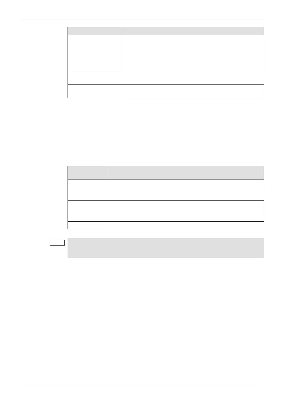
Frame Switch
Value
Description
0 Sirius 850: Only frame in a single frame system (576 x 1152)
1
Sirius 850: First frame in a two frame system expanded to 1152
2
.
(Outputs 1-576)
2
Sirius 850: Second frame in a two frame system expanded to 1152
2
.
(Outputs 577-1152)
3 Sirius 840
4 to 9 These positions are reserved for future use
Table 87 Frame ID Numbering
• If a Sirius 850 router installation is modified from a single frame system to a two
frame system (or back to a single frame system) the Frame ID will need to be
changed on each Sirius 850.