Sirius 800 Series User Manual Sirius 840/850: Alarm Rear Panel Connections Control and Alarm Rear Panel Connections 16.3
Iss 5 Rev 7 Page 296 © 2017 SAM
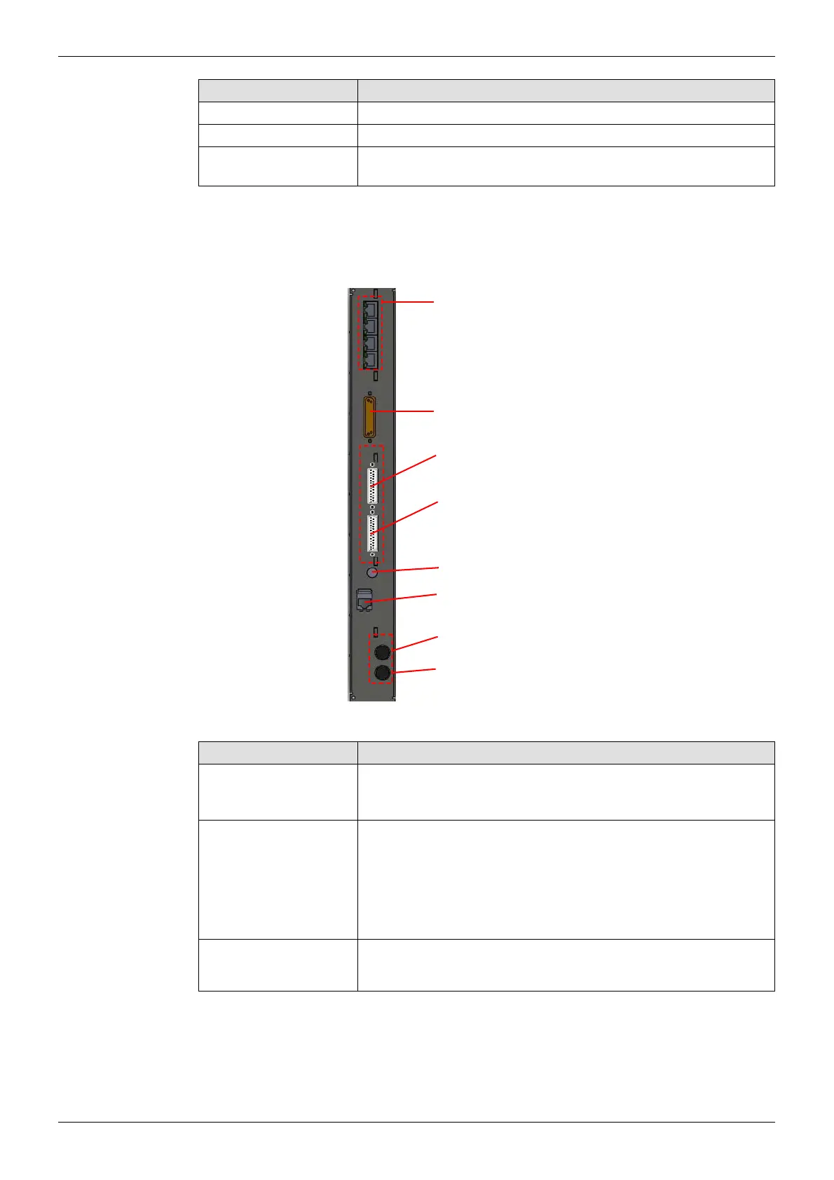
16.3 Sirius 840/850: Alarm Rear Panel Connections
The Alarm Rear Panel contains all the alarm control connectors for the Router.
Ethernet Not Used
EXP Not Used
Monitor Outputs 1 - 4 BNC x 4 - Supports 3G, SD, HD video and AES audio output
monitoring (see section 13.7 for configuration requirements)
Connector Function
Table 85 Control Rear Panel (Sirius 840/850)
Figure 191 Alarm Rear Panel Connections
Connector Function
4 x RJ45 Connectors Sirius 840 - Not Used
Sirius 850 - Used when expanding between two Sirius 850
frames, 12.2 for details
Alarms 25-Way D-Type socket - Alarm Outputs: Alarm outputs switch in
the event of the following failures: Fan, Controller, PSU. For
details on the output that switches for each failure see section
16.4.3.
For example the outputs can be used for warning lights in a panel
or monitoring by an external control system.
PSU Status B
PSU Status A
25 Way D-Type socket x 2 - PSU Alarm Inputs. Collects alarm
signals from the PSU(s), using the supplied cable(s)
Table 86 Sirius Alarm Rear Panel Connections
4 x RJ45 Connectors
Sirius 840 - Not Used
Sirius 850 - Used when expanding
between two Sirius 850 frames, see
section 12.2.1 for details
Alarms
PSU Status B
PSU Status A
Door Ethernet
Door Fuse
Spare Fuse
Frame ID