Saia-Burgess Controls AG
Manual I/O-modules for PCD1 │ PCD2 series │ Document 27-600 – Release ENG09 │ 2019-05-01
7-3
PCD2.B160 & PCD3.B160
Hardware
7
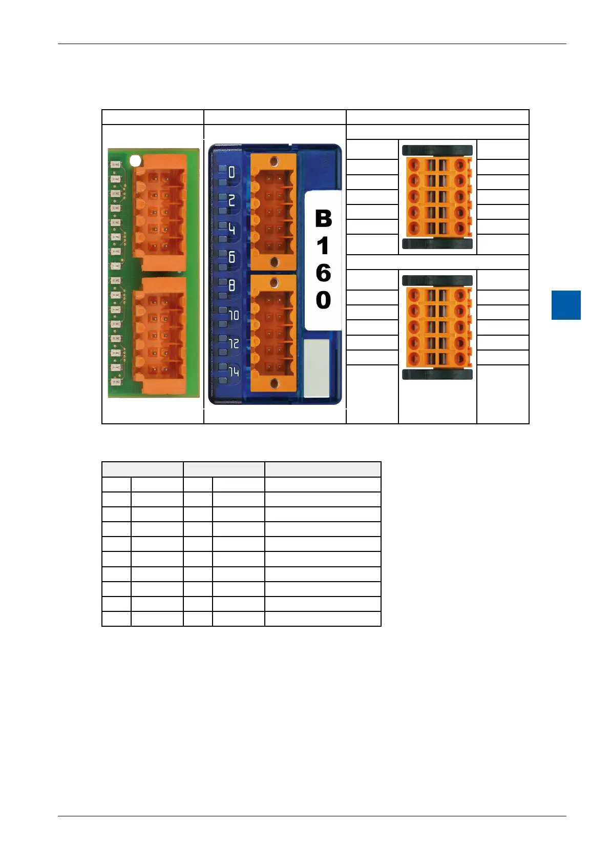
7.2.1 I/O connection
PCD2 PCD3 Description
X0 IO 0…7 X0 IO 0…7 Connector X0 Type K
I/O_0 0 1 I/O_1
I/O_2 2 3 I/O_3
I/O_4 4 5 I/O_5
I/O_6 6 7 I/O_7
GND 8 9 24 V
Connector X1 Type K
I/O_8 0 1 I/O_9
I/O_10 2 3 I/O_11
I/O_12 4 5 I/O_13
I/O_14 6 7 I/O_15
GND 8 9 24 V
X1 IO 8…15 X1 IO 8…15
X0 X1 Description:
0 IO_0 0 IO_8 Mixed In-/Output
1 IO_1 1 IO_9 Mixed In-/Output
2 IO_2 2 IO_10 Mixed In-/Output
3 IO_3 3 IO_11 Mixed In-/Output
4 IO_4 4 IO_12 Mixed In-/Output
5 IO_5 5 IO_13 Mixed In-/Output
6 IO_6 6 IO_14 Mixed In-/Output
7 IO_7 7 IO_15 Mixed In-/Output
8 GND 8 GND GND extern
9 24V 9 24V +24 V extern
7.2.2 LED signalization
The module has 16 LEDs. Each channel has its own LED.