1 -
7
GENERAL INFORMATION
TORQUE
The following tables list the tightening torque for the major fasteners, and the parts requiring use of a
non-permanent locking agent or liquid gasket.
Letters used in the “Remarks” column mean:
L: Apply a non-permanent locking agent.
MO: Apply molybdenum disulfi de oil solution (mixture of the engine oil and molybdenum disulfi de
grease in a weight ratio 10:1).
EO: Apply engine oil.
SS: Apply silicone sealant
Lh: Left-hand Threads
R: Replacement Parts
S: Follow the specifi c tightening sequence.
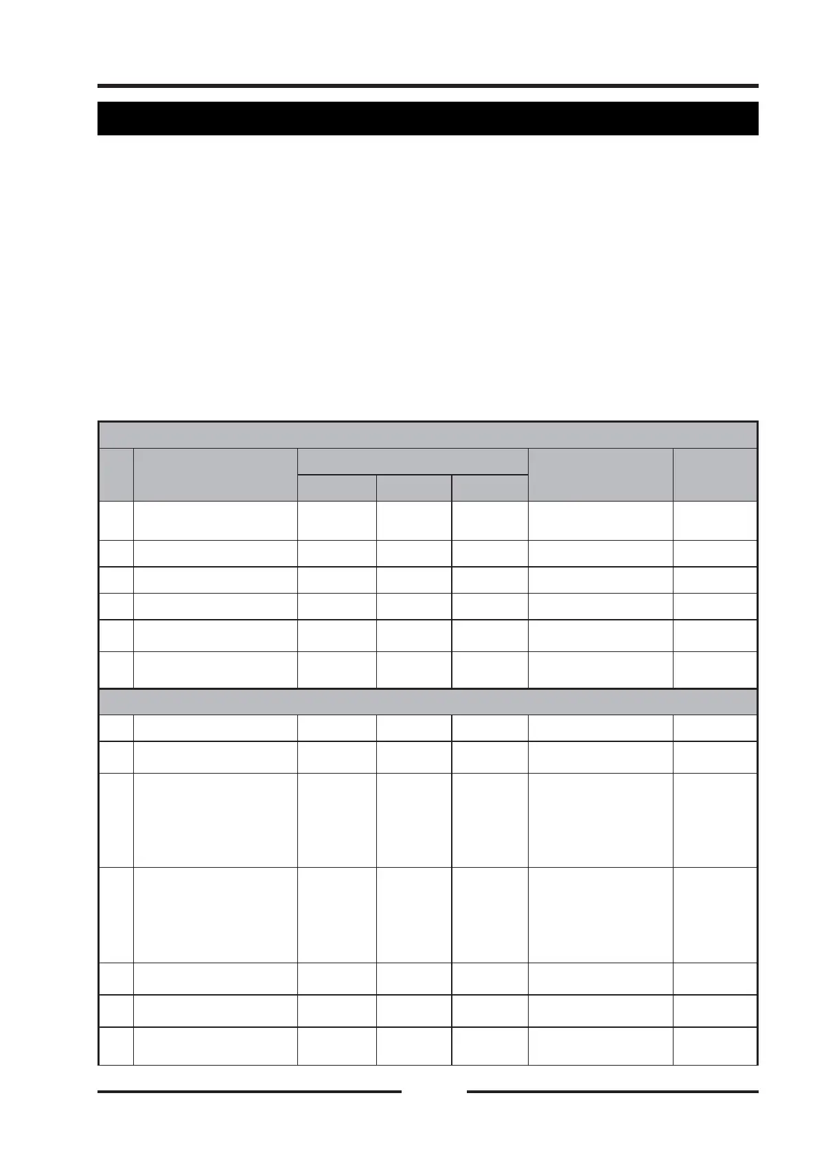
Engine standard fastener torque
NO.
Fastener
Torque
Fastening part
Remarks
N·m
kgf·m
ft·lb
1
Screw M6×16
8~12
0.8~1.2
69~103.6
in·lb
2
Screw M8×25
22~28
2.2~2.8
16.2~20.7
3
Screw M6×16
16~20
1.6~2.0
11.8~14.7
4
Screw M8×25
29~35
2.9~3.5
21.4~25.8
5
Hexagon fl ange bolt
M10×1.25×25
75~85
7.5~8.5
55.3~62.7
6
Hexagon fl ange bolt
M12×1.25×30
112~128
11.2~12.8
82.6~94.4
Engine special fastener torque
1 Bolt
M12×1.25×185
112~128
11.2~12.8
82.6~94.4
CVT Clutch primary
2 Bolt
M10×1.25×80
75~85
7.5~8.5
55.3~62.7
CVT Clutch
secondary
3
Cylinder head bolt
M11×1.25×150
1. 12
2. 35
3. Tighten
at 180°
angle
1. 1.2
2. 3.5
3. Tighten
at 180°
angle
1. 8.8
2. 25.8
3. Tighten
at 180°
angle
Cylinder head
assemble bolt
Through
three
tightening
4
Box bolt combination
M10×1.25×110
1. 12
2. 28
3. Tighten
at 90°
angle
1. 1.2
2. 2.8
3. Tighten
at 90°
angle
1. 8.8
2. 20.6
3. Tighten
at 90°
angle
Lower crankcase
assembly bolt
Through
three
tightening
5
Bolt M8×90
33~36
3.4~3.7
24~27
4 lower crankcases
bolts
6
Bolt M8×40
33~36
3.4~3.7
24~27
2 upper crankcase
bolts
7
Piston nozzle pressure
regulator
18~22
1.8~2.2
13~16
Upper crankcase
cylinder bore

 Loading...