Communication parameter group 07
PARAMETER DESCRIPTION 129
Set the address for sending information
Function code set by Master+H80
Set code in the following table
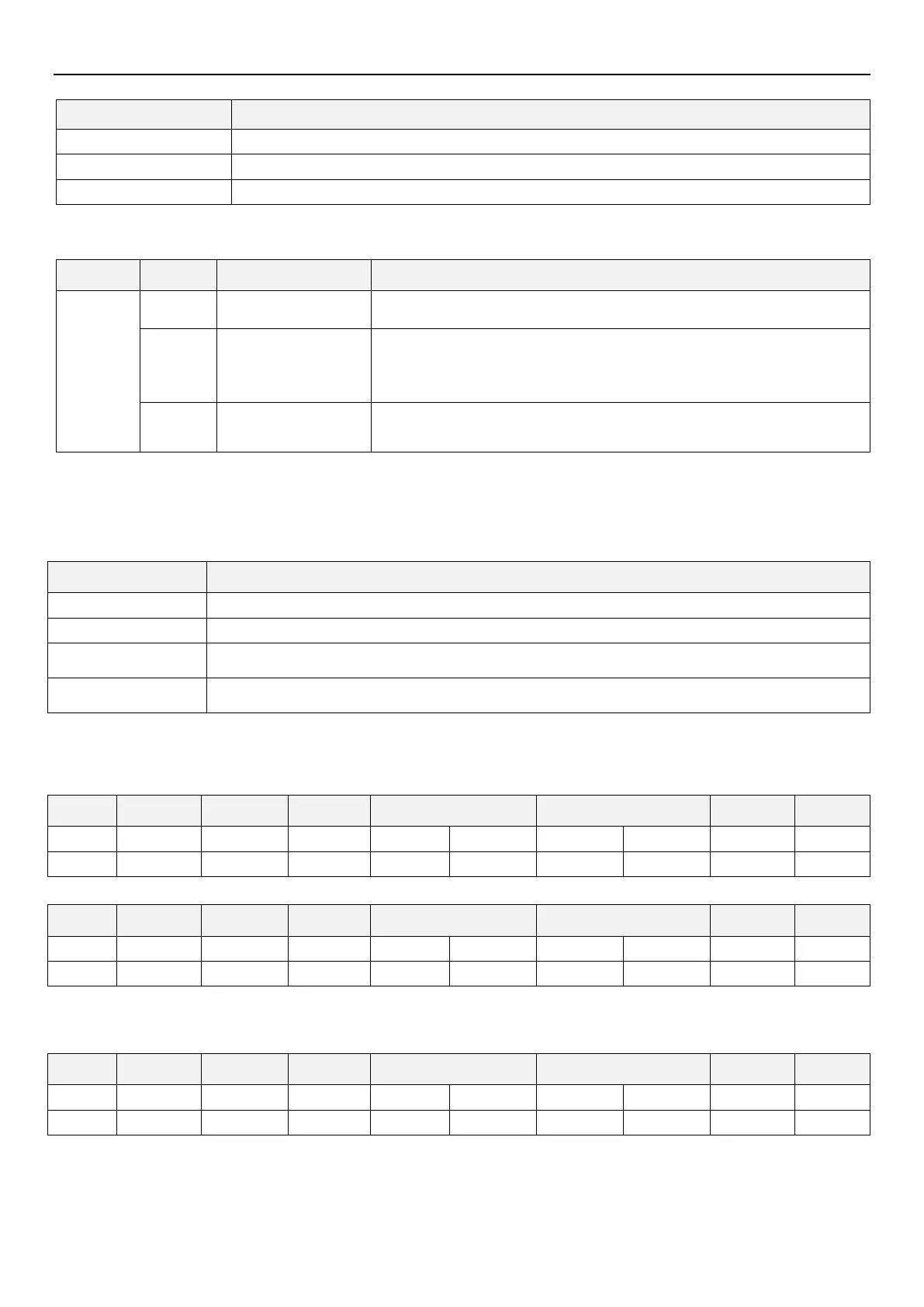
Error code list:
In query data sent by Master, the function code cannot be processed by slave
device. Function codes are not H03, H06, H08, H10 (Suppose).
In query data sent by Master, the address cannot be processed by Slave
(outside the addresses listed in the table, the reserved parameters, the
parameters not allowed to be read, the parameters not allowed to be written).
In query data sent by Master, the data cannot be processed by the Slave
(outside parameter writing range, required specified mode, other error, etc.).
Note: When read multiple parameters, if there is at least one readable data, it is not an error if there are reserved
parameters within.
In data sent by Master, Slave (inverter) will detect the following errors, but will not respond when it detects the error.
Error detection item table:
The parity test for data received by the inverter is different from the parity test set at the initial stage.
The stop byte of the data received by the inverter mismatches the stop byte set at the initial stage.
When the inverter is receiving data, the host computer sends the next set of data before the inverter
finishes receiving the current one.
The LRC/CRC calculated by the inverter according to the received data is different from the received
LRC/CRC.
Communication example
Example 1. CU operation mode written by communication
Step 1: Upper controller modifies operation mode of inverter
Step 2: After receiving and processing the data without error, inverter will send a reply to upper controller
Example 2. Read parameter 01-28(P.162)value by upper controller
Step 1: Upper controller sends message to inverter to read 01-28(P.162) value. 01-28(P.162) address is H00A2.

 Loading...

