Communication parameter group 07
PARAMETER DESCRIPTION 130
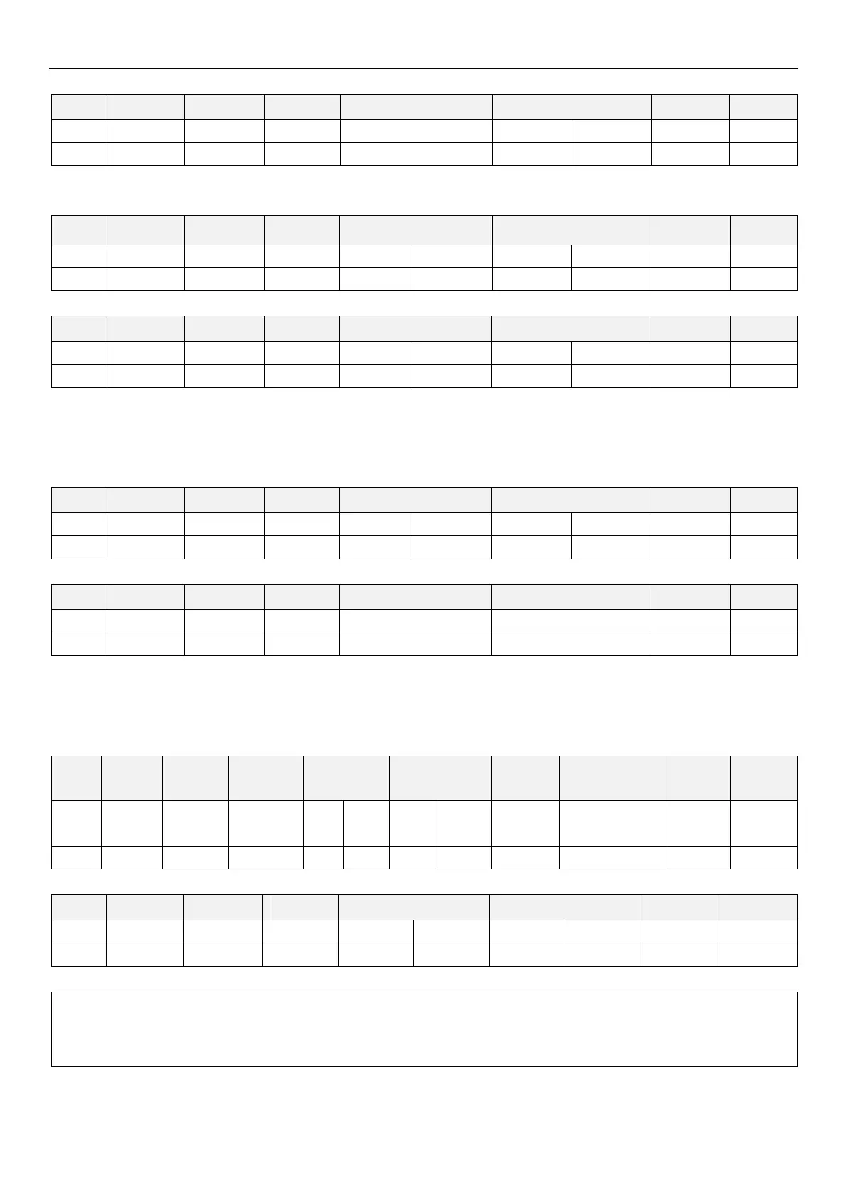
Step 2: After receive and processing the data without error, inverter will send 01-28(P.162) to upper controller.
Example 3. Upper controller change inverter 01-28(P.162) value to 50.
Step 1: Upper controller sends message to inverter to write 50 into 01-28(P.162).
Step 2: After receive and processing the data without error, inverter will send a reply to upper controller
Example 4. Upper controller read parameters 01-10(P.0), 01-00(P.1), 01-01(P.2), 01-03(P.3), 04-00~04-02/P.4~P.6,
01-06~01-07/P.7~P.8, 06-00(P.9),10-00~10-01/P.10~P.11.
Step 1: Upper controller sends message to inverter for reading 01-10(P.0), 01-00(P.1), 01-01(P.2), 01-03(P.3),
04-00~04-02/P.4~P.6, 01-06~01-07/P.7~P.8, 06-00(P.9), 10-00~10-01 /P.10~P.11 value. Start address is H0000.
Step 2: After receive and processing the data without error, inverter will send a reply to upper controller
Example 5. Upper controller write parameters 01-10(P.0), 01-00(P.1), 01-01(P.2), 01-03(P.3), 04-00~04-02/P.4~P.6,
01-06~01-07/P.7~P.8, 06-00(P.9), 10-00~10-01/P.10~P.11.
Step 1: Upper controller sends message to inverter for writing 01-10(P.0), 01-00(P.1), 01-01(P.2), 01-03(P.3),
04-00~04-02/P.4~P.6, 01-06~01-07/P.7~P.8, 06-00(P.9),10-00~10-01/P.10~P.11
Step 2: After receive and processing the data without error, inverter will send a reply to upper controller
Note: In above examples, parameters 01-28(P.162)reading and writing are all using P parameter mode. To use
parameter group mode, please note the difference in address. Please refer to the communication command list
for relevant contents.

 Loading...

