Digital input/ output parameter group 03
PARAMETER DESCRIPTION 91
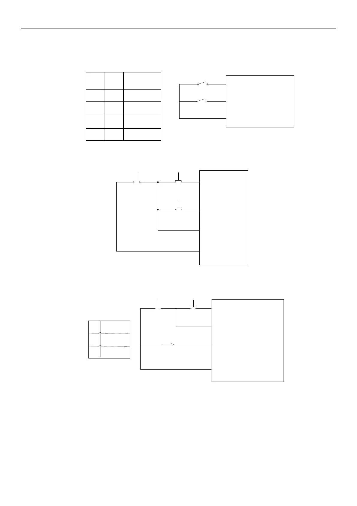
2) Two-wire control mode 2:
K0
K1
RUN(03-0X(P.8X)=28)
STF/STR(03-0X(P.8X)=29)
SD
K0 K1
Run
command
0
1
0
1
11
0
0
Stop
Forward
Reverse
Stop
3) Three-wire control mode 1 (with seal-in function): K0 is STOP, normal close. When trigger inverter will stop.
K1 is forward and K2 is reverse, normal open. All K0 K1 K2 are edge trigger button.
STOP(03-0X(P.8X)=31)
K0
K2
K1
STR(03-0X(P.8X)=1)
STF(03-0X(P.8X)=0)
SD
4) Three-wire control mode 2 (with seal-in function): K1 is STOP, normal close. When trigger inverter will stop. K2
is RUN, normal open. K1 K2 are edge trigger buttons. Change direction by STF/STR terminal, set value: 39. When
changing the direction, stop the inverter first, then switch K0 state and start inverter again.
STOP(03-0XP.8X=31)
K0
K2
K1
STF/STR(03-0XP.8X=29)
RUN(03-0XP.8X=28)
Run
command
Forward
Reverse
SD
K0
1
0
Set value: 33 PO(programmed operation):
When in external mode and PO is ON, inverter will be in programmed operation mode. Terminal STF is start.
When STF is ON, inverter run programmed operation mode at the first section. When STF is OFF, inverter stop.
Terminal STR is pause. When STR is ON, pause the operation. When STR is OFF, operation continues from
section before pausing. For details, please refer to 04-15(P.100), 04-27~04-42(P.101~P.118), 04-16~04-26
(P.121~P.123, P.131~P.138).
Set value: 35 MPO(manual programmed operation):
In external mode, when MPO is “on” run manual cycle operation. For details, please refer to 04-19~04-26
(P.131~P.138).

 Loading...

