5
05.01
5.1 Feed control with user–friendly and analog setpoint interface 6SN1118–0AA11–0AA1
5-103
Siemens AG 2001 All rights reserved
SIMODRIVE 611 Planning Guide (PJU) – 05.01 Edition
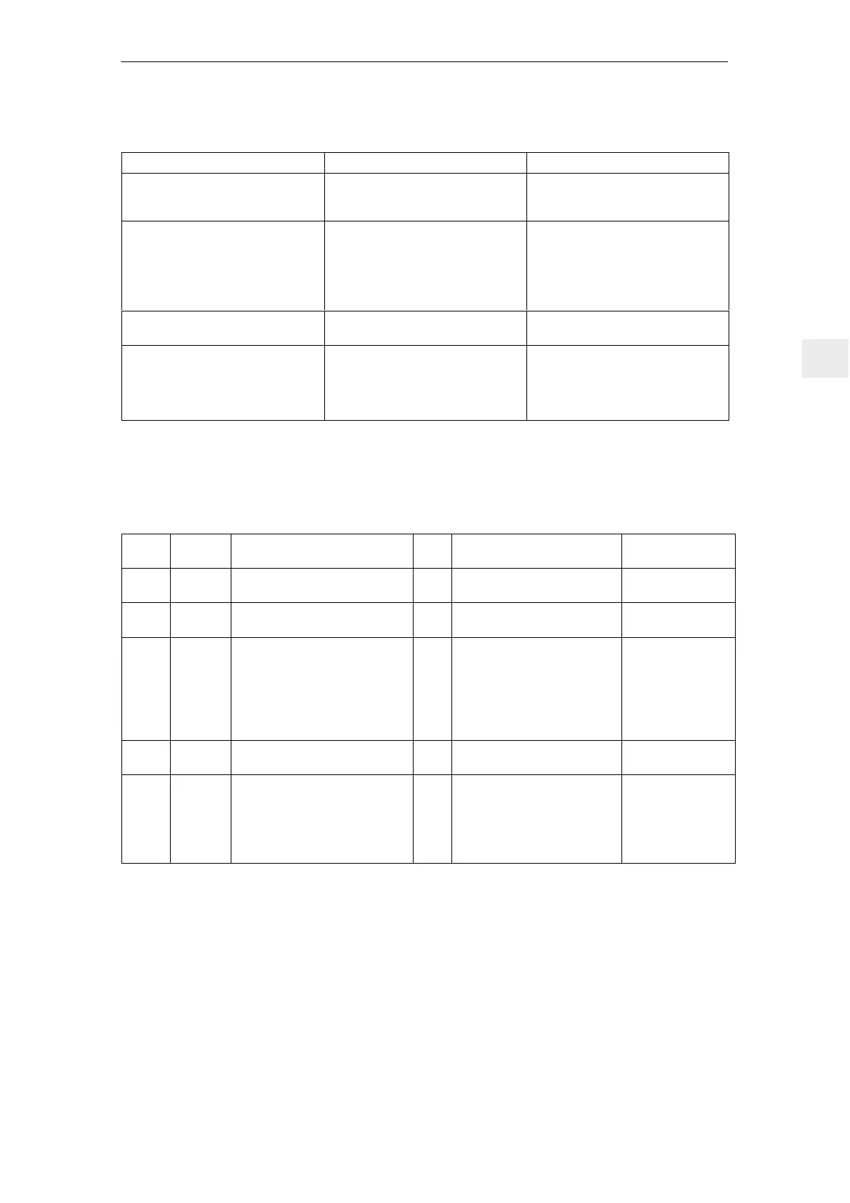
Table 5-2 (Fortsetzung)Function overview and settings using the 6SN1114–0AA01–0AA1 parameter module
Parameter Setting elementsValue range
Instantaneous controller/pulse inhibit
via terminal 65
Delayed after the speed controller
monitoring time has expired ↔
instantaneous
R13
Selection:
int. supplementary setpoint 1 through
terminal 22
Selection:
int. supplementary setpoint 2 through
terminal 23
10 V...+10 V
10 V...+10 V
R16, R17, R18=setpoint
R19, R21, R22=setpoint
Ready/fault signal at termi-
nals 672/673/674
R33
Smoothing:
Speed setpoint
Speed actual value
Speed controller
Current setpoint
T = C4 ⋅ 10 kΩ
T = C5 ⋅ 5 kΩ
T = C3 ⋅ 68 kΩ
T = C6 ⋅ 1 kΩ
C4
C5
C3
C6
5.1.2 Interface overview, feed control, user–friendly interface
Table 5-3 Interface overview, feed control, user–friendly interface
Term.
No.
Desig. Function
Type
1)
Typ. voltage/limit values Max. cross–sect.
56
14
X321
X321
Speed setpoint 1
Differential input
2)
I
I
0 V... ± 10 V 1.5 mm
2
1.5 mm
2
AS1
AS2
X331
X331
Checkback signal contact
Relay, start inhibit
NC
max. 250 V
AC
/1 A, 30 V
DC
/2 A 1.5 mm
2
1.5 mm
2
663
9
65
9
22
23
X331
X331
X331
X331
X331
X331
Pulse enable
3)
Enable voltage
3)6)
Controller enable
3)
Enable voltage
3)6)
Select int. fixed setpoint 1
3)
/
current–controlled operation
Select int. fixed setpoint 2
3)
I
O
I
O
I
I
+21...30 V
+24 V
+13...30 V
+24 V
+13...30 V
+13...30 V
1.5 mm
2
1.5 mm
2
1.5 mm
2
1.5 mm
2
1.5 mm
2
1.5 mm
2
20
24
X331
X331
Speed setpoint
2)
/ current setpoint
(differential input)
I
I
0 V...±10 V
(340 µs smoothing)
1.5 mm
2
1.5 mm
2
96
5)
44
5)
6
5)
258
5)
16
5)
X331
X331
X331
X331
X331
Current setpoint limiting
Electronics voltage
Integrator inhibit, speed
controller
Current setpoint (master/slave)
Norm. current actual value
I
O
I
I/O
O
0...±30 V
–15 V/10 mA
+13...30 V
0 V...±10 V
0 V...±10 V
1.5 mm
2
1.5 mm
2
1.5 mm
2
1.5 mm
2
1.5 mm
2
1) I=input; O=output; NC=NC contact; NO=NO contact (for signal NO=high/NC=low)
2) Differential input reference point
The common mode range of the differential input is24 V with respect to PE potential and may not
be exceeded.
3) Reference ground, terminal 19 NE/monitoring module (this may not be connected with the general reference
ground, terminal 15)
4) Voltages referred to PE potential
5) Terminal 15 on the NE module is the reference ground
6) Refer to Section 6.3
5 Control Modules

 Loading...


