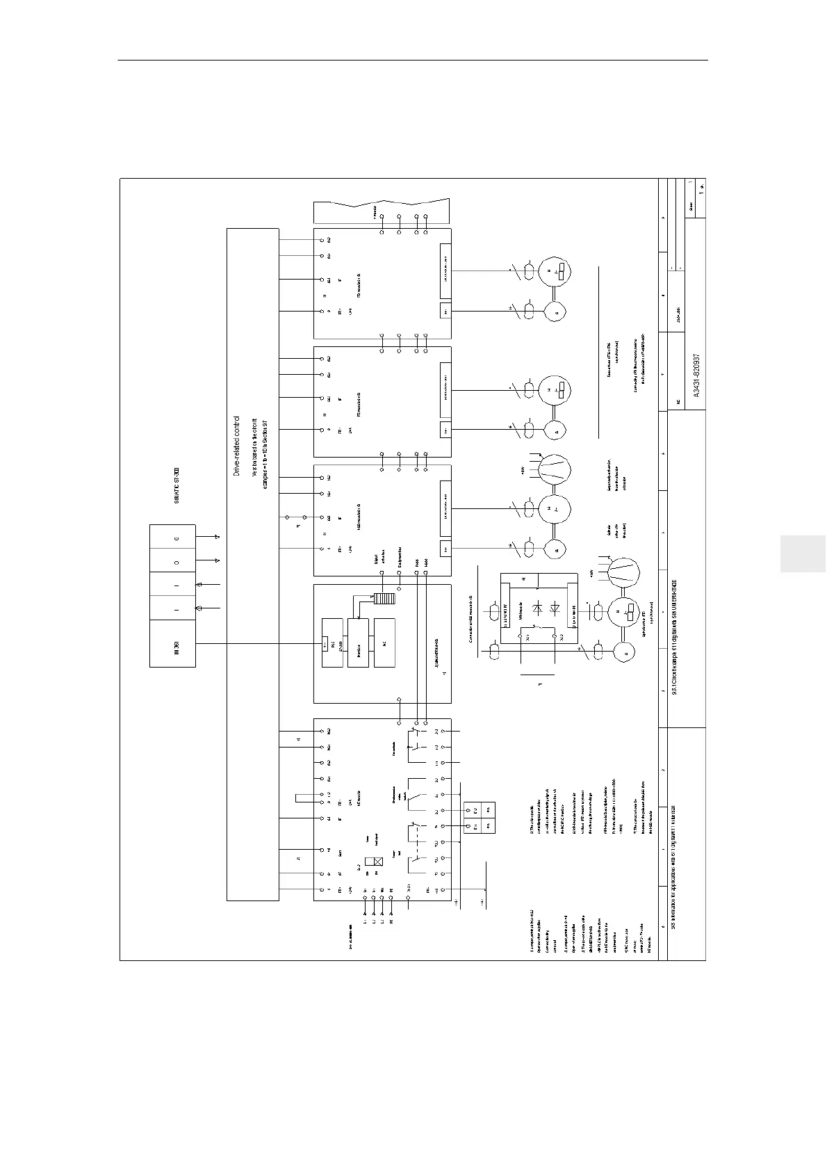
Home
Siemens
Media Converter
Simodrive 611
Siemens Simodrive 611 Planning Guide
4
of 1
of 1 rating
380 pages
Give review
Manual
Specs
To Next Page
To Next Page
To Previous Page
To Previous Page
Loading...
9
05.01
9.8
Information on applications with 61
1 digital/61
1 universal
9-281
Siemens AG 2001 All rights reserved
SIMODRIVE 61
1 Planning Guide (PJU)
–
05.01 Edition
9.8
Information
on applications with 61
1 digital/61
1 universal
Fig.
9-24
Circuit example 61
1 digital with SINUMERIK 840D
9 Important Circuit Information
280
282
Table of Contents
Table of Contents
11
Overview of SIMODRIVE 611
17
Overview of the Drive System
17
Engineering Steps
21
Block Diagrams
22
System Configuration
23
Module Arrangement
24
Ambient Conditions
25
Motor Selection
26
Direct Position Sensing
27
Position Sensing/Speed Actual Value Sensing
27
Indirect Position Sensing
29
Drive Modules
30
Power Modules
30
Connecting the Power Modules
31
Function of the Power Modules
31
Control Modules
32
Drive Module with SIMODRIVE 611 Universal
32
Drive Modules with Induction Motor Regulation
32
Control Modules for 1FT5 Motors with Analog Setpoint Interface for Feed Drives
33
Control Modules with Analog Setpoint Interface and Motion Control with PROFIBUS-DP SIMODRIVE 611 Universal E
33
Control Modules for 1FK6 and 1FT6 Motors with Resolver and Analog Setpoint Interface for Feed Drives
34
Control Modules for 1PH Induction Motors with Analog Setpoint Interface for Main Spindle Drives
34
Control Modules with Analog Setpoint Interface for Induction Motors
35
Control Modules with Digital Setpoint Interface for FD and MSD
35
Control Modules with Digital Setpoint Interface for Hydraulic/Analog Linear Drives HLA/ANA
36
NCU Box for SINUMERIK 840D
37
Infeed Modules
38
Cooling Components
39
Dimension Drawings
40
Internal Cooling
41
External Cooling
42
Overvoltage Limiting Module
44
HF Commutating Reactor
46
Line Filter
46
Line Filter Packages
46
Line Supply Connection
46
Line Supply Connection for Voltage Adaptation
46
Line Supply Types
47
Transformers
53
Motor Protection
55
Motor Selection
55
Motor Selection, Position/Speed Sensing
55
Motors with Holding Brake
55
Direct Position Sensing
56
Encoder Systems Which Can be Evaluated
56
Indirect Position and Motor Speed Sensing
56
Motor Encoder
56
Encoder Power Supply
61
Encoder Power Supply for SSI Encoders
64
3.5 Overview, Position Sensing
66
Features and Technical Data
75
High-Resolution Position (HGL)
75
Connector Assignment
76
System Configurations and Cable Connections
77
Ordering Information
79
Power Modules
81
Technical Data
83
Technical Data, Power Modules
83
Current De-Rating
88
Information on the Motor-Drive Converter Selection, MSD Analog
89
Information on the Motor-Drive Converter Selection, IM Analog
90
Information on Motor-Converter Selection, FD Control, Digital
91
Information on Motor-Converter Selection MSD Control, Digital
92
Information on the Motor-Converter Selection IM Control Digital
93
Technical Data of the Supplementary Components
95
Load Duty Cycle Definitions, Drive Modules
96
Interface Overview
97
Control Modules
99
Feed Control with User-Friendly and Analog Setpoint Interface
101
6Sn1114-0Aa01-0Aa1
102
Function Overview and Settings Using the Parameter Board
102
Interface Overview, Feed Control, User-Friendly Interface
103
Option Module, Main Spindle Functions 6SN1114-0AA02-0AA0
105
Interface Overview, MSD Option
106
5.2 Feed Control with Standard Interface and Analog Setpoint Interface 6SN1118-0A_11-0AA1
107
6Sn1118-0A_11-0Aa1
108
Function Overview and Settings on the Control Module
108
Interface Overview, Feed Control, Standard Interface
109
6Sn1118-0B_11-0Aa0
110
Resolver Control with Standard and Analog Interface
110
Function Overview and Settings
111
Interface Overview, Resolver Control
112
5.4 Main Spindle Control with Analog Setpoint Interface 6SN1121-0BA1_-0AA
114
Select Terminal Functions
115
Select Relay Functions/Signals
116
Interface Overview, Main Spindle Control
117
5.5 Induction Motor Control with Analog Setpoint Interface 6SN1122-0BA1_-0AA
118
Select Terminal Functions
119
Select Relay Functions/Signals
120
Interface Overview, Induction Motor Control
121
Drive Control with Digital Setpoint Interface
124
Interface Overview, Drive Control
126
Control Module "SIMODRIVE 611 Universal
127
Control Module for 1 or 2 Axes
129
Description of the Terminals and Interfaces
132
Control Module "SIMODRIVE 611 Universal E
136
Control Module with Option Module
137
Description of the Terminals and Interfaces
138
Control Module "HLA Module
143
System Overview
145
Wiring
147
Test Sockets (Diagnostics)
152
Control Module "ANA Module
153
System Overview
154
Wiring
156
Bus Interfaces
160
Infeed Modules
161
Function Overview and Settings
165
Power Modules Operated from an Uncontrolled Infeed
169
Technical Data
171
Technical Data, Line Supply Infeed Modules
173
Technical Data of the Supplementary Components
175
Interface Overview
177
Interface Overview, NE Modules
177
Interface Overview, 5 Kw UI Module
180
Monitoring Module
182
System Integration
182
Mode of Operation
184
Checking the Permissible Power Supply Rating
186
Technical Data (Supplements the General Technical Data)
186
Capacitor Module with 4.1 Mf or 20 Mf
191
DC Link Options
191
Overvoltage Limiting Module
197
Pulsed Resistor Module
197
External Pulsed Resistors
198
Line Supply Connection
203
HF Commutating Reactors
204
Assigning Commutating Reactors to the NE Modules
205
Assigning Transformers to the I/R Modules
208
Assigning Transformers to the UI Modules
210
Assigning Main Switches
211
Line Filter and HF Commutating Reactors for I/R and UI Modules
212
Assigning the Line Filters to the I/R Modules
214
Assignment of the Line Filters to the UI Modules
215
Supplementary System Components
217
Connecting Cable for 2–Tier Arrangement
218
Important Circuit Information
219
Infeed Modules
222
Description of the Interfaces and Functions
223
Connecting Several NE Modules to a Main Switch
229
Use, Mode of Operation and Connection of the Line Contactor
230
Timing Diagram for the Ready Signal in the I/R Module
231
Sequence Diagram, Central Signals at the NE Module
232
Axis Expansion Using the Monitoring Module
233
Connection Example, Pulse Enable
234
Description of the Interfaces and Functions
235
Drive Modules
237
Description of the Interfaces and Functions
238
Start Inhibit in the Drive Modules
240
Mode of Operation of the Start Inhibit
241
Sequence and Procedure When Using the Start Inhibit
242
Checking the Start Inhibit
243
Application Examples with SIMODRIVE 611
244
Function Description, Application Example
245
Safety Technology and Standards
248
Circuit Examples =1 to =10 with SIMODRIVE 611 Analog
250
Function Description, Circuit Examples =1 to =10
265
Information on Applications with 611 Digital/611 Universal
281
Circuit Example 611 Digital with SINUMERIK 840D
282
Circuits with 611 Universal
283
Master/Slave Operation SIMODRIVE 611 Analog
284
Star–Delta Operation
285
Induction Motor Operation 611A (611D/611U)
289
Motor Changeover, Individual Induction Motors 611 Analog
291
Operation at Power Failure
293
DC Link Buffering
299
Special Applications
301
SINUMERIK Safety Integrated
302
Cabinet Design and EMC
305
Shield Connecting Plates
308
Internal Cooling
309
Two–Tier Unit Arrangement
310
Wiring
312
Block Diagrams
315
Connection Diagrams
317
Drawings
321
A EC Declaration of Conformance
364
B Abbreviations and Terminology
370
C References
372
Other manuals for Siemens Simodrive 611
Diagnostic Manual
880 pages
Configuration Manual
236 pages
Installation Guide
4 pages
4
Based on 1 rating
Ask a question
Give review
Questions and Answers:
Need help?
Do you have a question about the Siemens Simodrive 611 and is the answer not in the manual?
Ask a question
Siemens Simodrive 611 Specifications
General
Brand
Siemens
Model
Simodrive 611
Category
Media Converter
Language
English
Related product manuals
Siemens SIMODRIVE 611 digital
436 pages
Siemens SIMOTRAS 6SG7050
604 pages
SIMOVERT 6SE7024-1EB85-0AA0
106 pages
SIMOVERT MASTERDRIVES 6SE70 P Series
58 pages
Siemens SINAMICS DCM
758 pages
Siemens SINAMICS G150
1842 pages
Siemens SINAMICS S110
268 pages
Siemens SINAMICS G120X
1148 pages
Siemens SINAMICS G110M
428 pages
Siemens SINAMICS Series
758 pages
Siemens SINAMICS G120XA
918 pages
Siemens SINAMICS G120C USS/MB
470 pages