9
05.01
9.11 Induction motor operation 611A (611D/611U)
9-291
Siemens AG 2001 All rights reserved
SIMODRIVE 611 Planning Guide (PJU) – 05.01 Edition
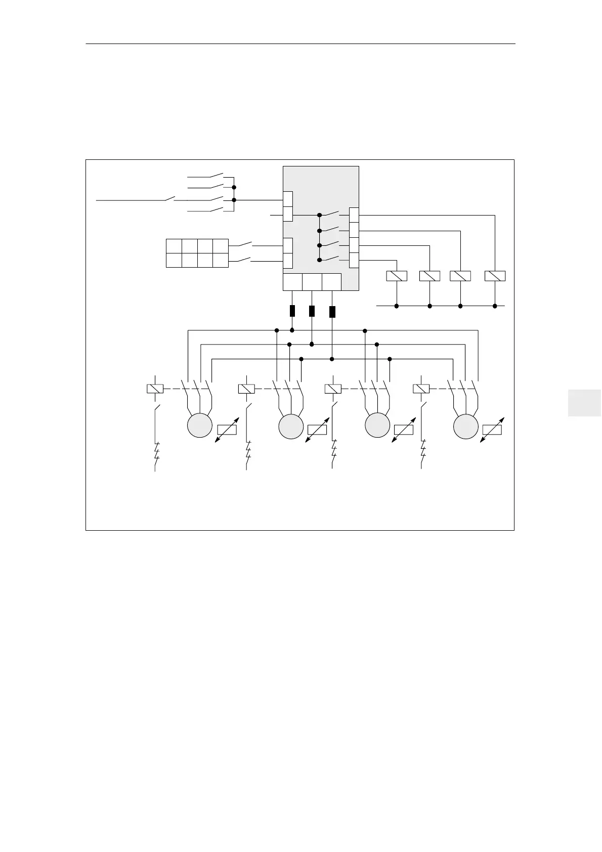
9.11.2 Motor changeover, individual induction motors 611 analog
The SIMODRIVE 611 IM module allows up to four different motors to be chan-
ged over. Each motor has a dedicated motor parameter set.
SIMODRIVE
611 IM
T.663
1) Several motors cannot be simultaneously controlled as this interlocked in the software.
In addition, the recommended contactor interlocking ensures that only one motor
can be operated.
2) Only required for high–speed special motors.
Pulse enable
Motor 1 Motor 2 Motor 3 Motor 4
K1
M1
3 ~
K1
K2
K3
K4
Select terminal input
En
En + 1
2)
K2
M2
3 ~
K
1H
K
2
K
3
K
4
K
2H
K
1
K
3
K
4
K
3H
K
1
K
2
K
4
K3
M3
3 ~
K4
M4
3 ~
K
4H
K
1
K
2
K
3
Output terminals
P24
U2 2 W V2
Az1
Ay1
Ax1
Aw11)
0
0
1st input
2nd input
Motor selection 1 2 3 4
1
0
0
1
1
1
K
1H
K
2H
K
3H
K
4H
0 V
PTC PTC PTCPTC
Fig. 9-30 Motor changeover at the SIMODRIVE 611 IM module
For motor changeover, an auxiliary contactor 3RH11 and a main contactor
3RT10 are required for each motor.
A binary–coded switching command is connected to select input terminals
En/En + 1 (max. two terminals for four motors) to changeover a motor. The
changeover command is only executed when the drive pulses are inhibited. In
this case, one of the terminals 663, 65 or 81 (function: Pulse inhibit) must be
opened. After the pulses have been inhibited, the active motor parameter set is
loaded and the motor auxiliary contactors controlled via select relay.
9 Important Circuit Information

 Loading...


