4
05.01
4.2 Current de–rating
4-90
Siemens AG 2001 All rights reserved
SIMODRIVE 611 Planning Guide (PJU) – 05.01 Edition
4.2.2 Information on the motor–drive converter selection, IM analog
The converter must be selected according to the required duty cycle.
Further, the following restrictive conditions must be observed:
S The motor no–load current must be less than the rated current of the drive
converter module (IM according to Table 4-6).
S As result of the current actual value resolution, the lowest no–load motor
current must fulfill the following condition:
w
n
max
n
FS
I
0Mot
I
min
(I
min
according to Table 4-6)
Various inverter clock frequencies can be parameterized; observe the current
de–rating.
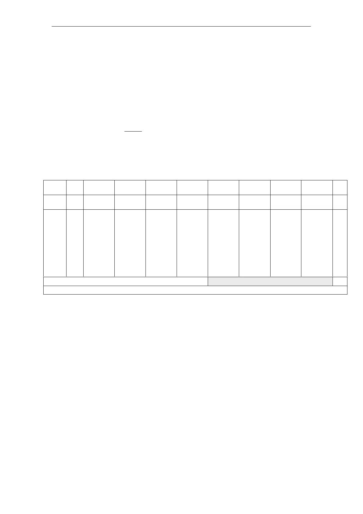
Table 4-6 Inverter clock frequency IM analog f
0
=3.2 kHz: Currents as a function of the inverter clock frequency f
T
In/Is6/Imax
in A
In/Is6/Imax
in A
In/Is6/Imax
in A
In/Is6/Imax
in A
In/Is6/Imax
in A
In/Is6/Imax
in A
In/Is6/Imax
in A
In/Is6/Imax
in A
Imin
in A
PM
type
Code
No.
f
T
3.20 kHz
f
T
4.70 kHz
f
T
6.30 kHz
f
T
7.80 kHz
f
T
2.80 kHz
f
T
3.90 kHz
f
T
5.00 kHz
f
T
5.90 kHz
LT 8A
LT 15A
LT 25A
LT 50A
LT 80A
LT 108A
LT 120A
LT 160A
LT 200A
LT 300A
LT 400A
1
2
3
6
7
13
8
9
10
11
12
3/3/3
5/5/8
8/10/16
24/32/32
30/40/51
45/60/76
45/60/76
60/80/102
85/110/127
120/150/193
200/250/257
2.5/2.5/2.5
4.2/4.2/6.8
6.9/8.6/13.8
20/26/26
26/34/44
39/52/65
39/52/65
51/68/86
73/95/109
101/127/163
169/211/217
2.0/2.0/2.0
3.4/3.4/5.4
5.7/7.1/11.4
15/20/20
21/28/36
32/43/54
32/43/54
41/54/69
60/78/90
81/102/131
135/169/174
1.6/1.6/1.6
2.6/2.6/4.2
4.6/5.7/9.1
10/14/14
17/23/29
26/34/43
26/34/43
31/42/53
48/63/72
62/78/101
104/130/134
3/3/3
5/5/8
8/10/16
24/32/32
30/40/51
45/60/76
45/60/76
60/80/102
85/110/127
120/150/193
200/250/257
2.8/2.8/2.8
4.6/4.6/7.4
7.4/9.3/15.0
22/29/29
28/37/48
42/56/71
42/56/71
56/74/95
79/103/119
111/139/179
185/232/238
2.4/2.4/2.4
4.1/4.1/6.5
6.7/8.3/13.3
19/25/25
25/33/42
37/50/63
37/50/63
49/65/83
71/91/106
98/122/157
163/203/209
2.2/2.2/2.2
3.6/3.6/5.8
6.0/7.5/12.0
16/21/21
22/30/38
34/45/57
34/45/57
43/58/73
63/82/95
86/108/139
144/180/185
0.6
1.1
1.8
3.6
5.7
8.5
11.3
11.3
14.1
21.2
28.3
up to including FW 2.xx
from FW 3.0
I
N
Rated module current at the converter pulse frequency
(standard value: f
0
3.2 kHz)
I
min
Minimum motor current
I
S6
Max. motor current for an S6 load duty cycle
I
Short
Short–time limiting current of the module used in A
rms
I
0Mot
No–load motor current in A
rms
n
FS
Speed at the start of field weakening
n
max
Maximum motor speed
S For motors with a low leakage induction, it may be necessary to provide a
series reactor and/or increase the inverter clock frequency of the drive con-
verter. From experience, motors with low leakage induction are those which
can achieve high stator frequencies (maximum motor stator frequency
>
300 Hz) or motors with a higher rated current (rated current > 85 A).
4 Power Modules

 Loading...


