9
05.01
9.4 Drive modules
9-237
Siemens AG 2001 All rights reserved
SIMODRIVE 611 Planning Guide (PJU) – 05.01 Edition
9.4 Drive modules
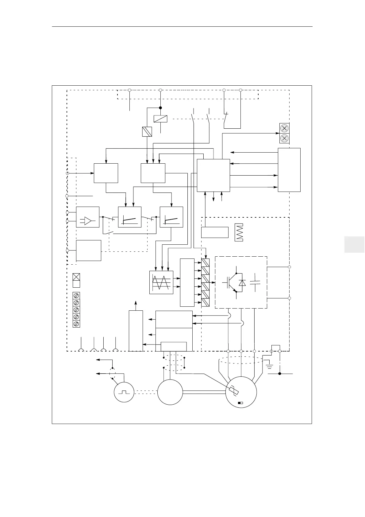
9.4.1 Block diagram, 611 analog feed module with standard interface
X351
X151
Equip-
ment
bus
H1
H2
Pulse
inhibit
65
X331
RF
9 24V
Monitoring
56
14
X321
663 AS1 AS2
Relay,
start inhibit
24 V, 15 V, 5 V
Equipment enable
Temperature
pre–alarm
Ready/fault
signal
2)
Checkback signal,
start inhibit
Pulse enable,
start inhibit
Optocoupler,
fast pulse inhibit
P600
M600
Closed–loop control
Power section
Current
rectification
Tachometer
rectification
X311
Motor tempera-
ture monitoring
Setpoint
22
Current–
controlled
operation
OFF: Ready signal
ON: Fault message
S3.6
Drift
Tachometer
K
p
T
N
Adaptation
1
X34
Mn
act
I
act
I
set
X35
21 2
PE
UVW
Motor encoder, rotor position/
tachometer
Servomotor
1FT5
Position encoder
(option) Indirect or direct
measuring system
T > T
max
9
PE1PE2
2
W
V2U2
Pulse distribution
Position
actual
value
To the NC /
positioning
control
1)
1) Can be set at
the front
2) Can be set at
the module
Controller
inhibit
M
3
syn
Temperature sensor
RLG
+
Tach.
Fault
Speed
controller
Current
controller
1)
Fig. 9-8 Block diagram, FD module with standard interface
9 Important Circuit Information

 Loading...


