6
05.01
6.4 Interface overview
6-177
Siemens AG 2001 All rights reserved
SIMODRIVE 611 Planning Guide (PJU) – 05.01 Edition
6.4 Interface overview
Note
Only PELF or SELF voltages may be connected (refer to EN 60204–1 Section
6.4).
Order Nos. for the coding connector, refer to Catalog NC60.
Only PELV circuits may be connected to terminal 19.
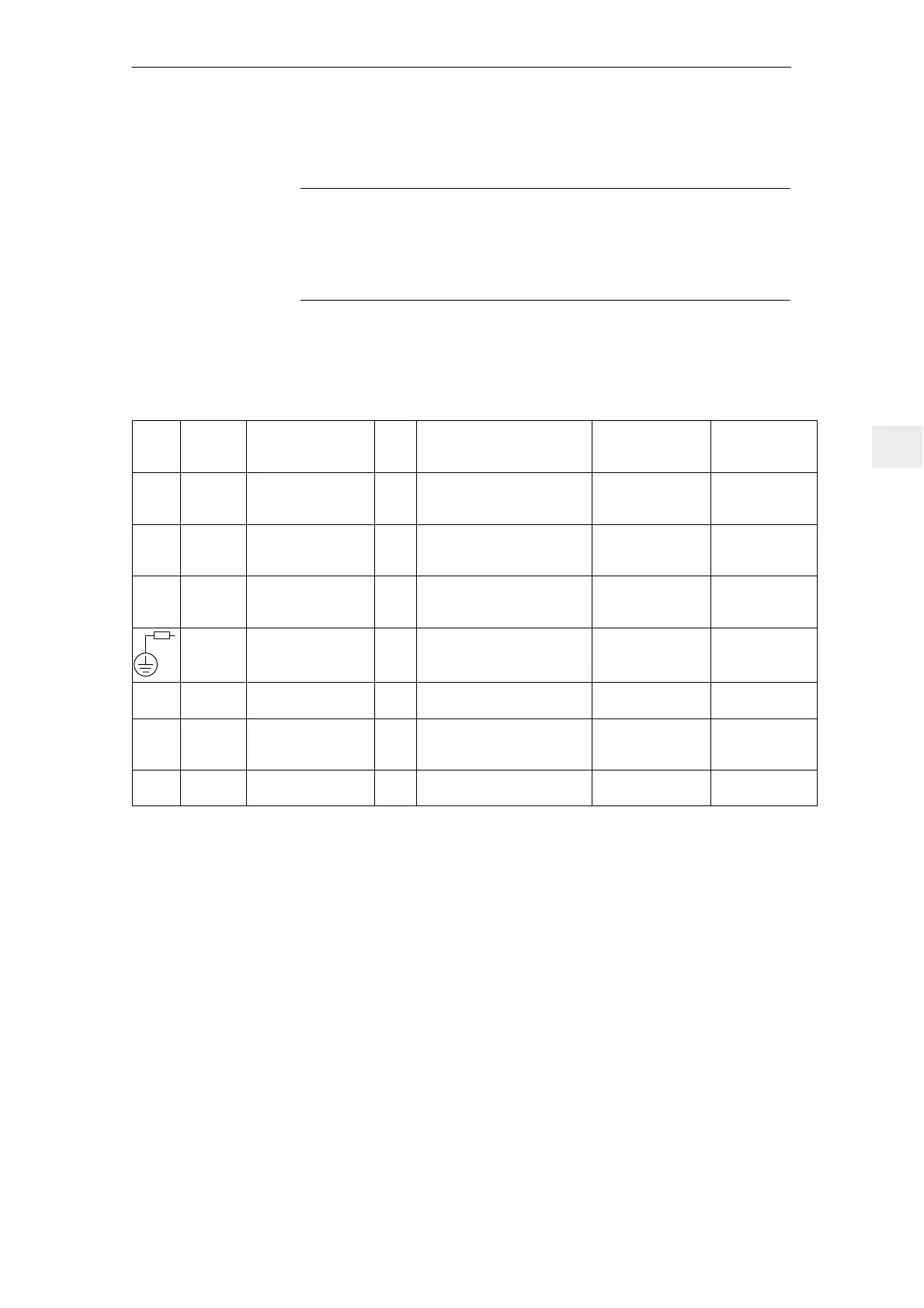
6.4.1 Interface overview, NE modules
The interface description is valid for all NE modules with the exception of the 5
kW UI module; this interface has its own description (refer to Section 6.4.2).
Table 6-6 Interface description for NE modules
Term.
No.
Desig. Function
Type
1)
Typ. voltage/ limit values
Max. cross–
section
10)
Terminals
available in
3)
U1
V1
W1
Supply connection I 3–ph. 400 V AC Refer to
Section 4.2 I/R, UI
L1
L2
Contactor supply I
I
2–ph. 400 V AC, directly from
the supply
L1, L2, L3, refer to Sect. 9.2
16 mm
2
/10 mm
2
4)
16 mm
2
/10 mm
2
4)
I/R 80 kW,
120 kW
PE
P600
M600
Protective conductor
DC link
DC link
I
I/O
I/O
0 V
+300 V
–300 V
Bolt
Busbar
Busbar
I/R, UI, monito-
ring module,
pulsed resistor
Grounding bar
5)
I/O –300 V Busbar I/R, UI
P600
M600
DC link
DC link
I/O
I/O
+300 V
–300 V
16 mm
2
/10 mm
2
4)
16 mm
2
/10 mm
2
4)
Monitoring
module
11)
1R,
2R,
3R
TR1,
TR2
9)
External resistance
connection
I/O V300 6 mm
2
/4 mm
2
4)
Pulsed resistor;
UI 28 kW
X131 Electronics M I/O 0 V 16 mm
2
/10 mm
2
4) I/R, UI, monito-
ring module
1) I = input; O = output; NC = NC contact; NO = NO contact; (for signal, NO = high; NC = low)
2) Terminal 19 is the reference ground (connected in the module with 10 k to a general reference ground,
X131/terminal 15)
Terminal 15 may neither be connected to PE nor to terminal 19, furthermore, it is not permissible
that external voltage sources are connected to terminal 15. Terminal 19 may be connected to terminal X131.
The terminal may only be used to enable the associated drive group.
3) I/R = Infeed/regenerative feedback module; UI = Uncontrolled infeed; MM = Monitoring module;
PW = Pulse resistor module
4) The 1st number is valid for cable lugs. The 2nd number is valid for finely–stranded conductors without conn. sleeves.
5) The grounding bar is used to ground the DC link M rail through 100 kΩ (this should be preferably inserted;
if the system is subject to a high voltage test, the grounding bar should be opened).
6) RESET = reset the fault memory, edge–triggered for the complete drive group (terminal ”R” terminal 15 = RESET)
7) Terminal 111–213 positively–driven NC contact (for I/R 16 kW and UI 10 kW, only from Order No. [MLFB]:
6SN114V–1VV01–0VVV)
Terminals 111–113 NO contact, not positively driven
8) Maximum current load of terminal 9 with respect to 19: 0.5 A.
9) Only for UI 28 kW
10) For UL certification, only use copper cables designed for an operating temperature of w 60
v
v
6 Infeed Modules

 Loading...


