2 System Configuration
2
05.01
2.7 Infeed modules
2-42
Siemens AG 2001 All rights reserved
SIMODRIVE 611 Planning Guide (PJU) – 05.01 Edition
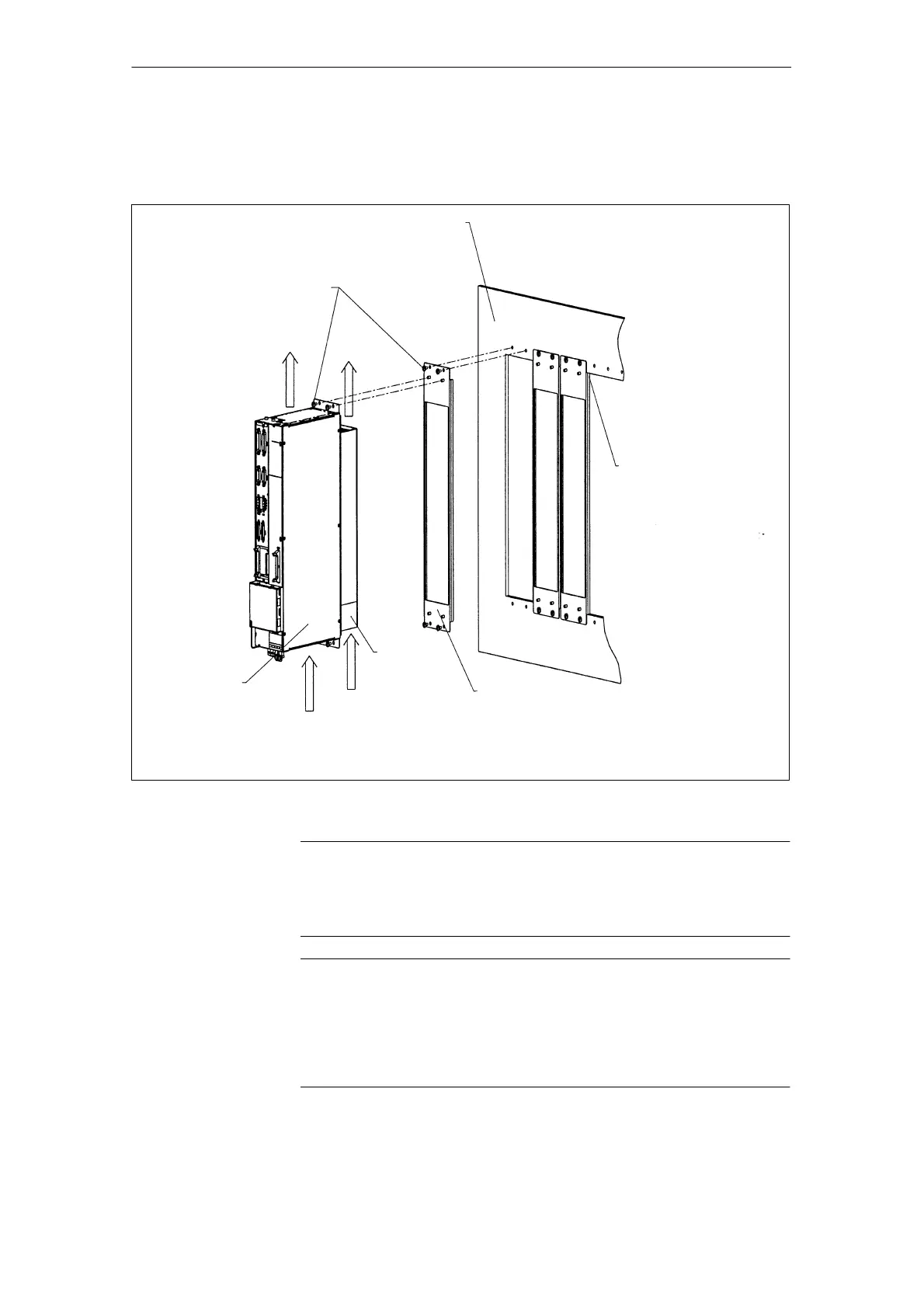
2.7.3 External cooling
Rear cabinet panel
(bare metal)
Air intake for the
electronics T40
0
C
Air intake for
the heatsink T40
0
C
Discharged air
electronics
Discharged
air, heatsink
Closed-loop control
Power module with
external cooling and
heatsink seal
M5 screw
Tightening torque 3 Nm
Fan assembly
Mounting frame
Note: Observe the air flow direction as shown in the diagram and
the ventilation clearance shown in dimension drawing, Section 13.
Dimension, mounting frame
according to the dimension sheet,
Section 13. Seal the mounting
frames with respect to one
another and to the rear cabinet
panel (e.g. using Terostat–91
from the Teroson company)
The sealing compound should be
applied around the circumference
so that degree of protection IP54 is
guaranteed.
Fig. 2-7 Power module with inserted control module, external cooling
Note
Observe the direction of the airflow according to the diagram and clearance for
the cooling air in accordance with the dimension drawing, Section 13. Dimen-
sions, mounting frame according to the dimension drawing, Section 13.
Notice
For external heatsinks and fans, large amounts of accumulated dirt can have a
negative impact on the module cooling. The temperature monitoring function in
the power module can respond. The heatsink and fan must be checked for dirt
accumulation at regular intervals.
Clean as required!

 Loading...


