9
05.01
9.2 Infeed modules
9-229
Siemens AG 2001 All rights reserved
SIMODRIVE 611 Planning Guide (PJU) – 05.01 Edition
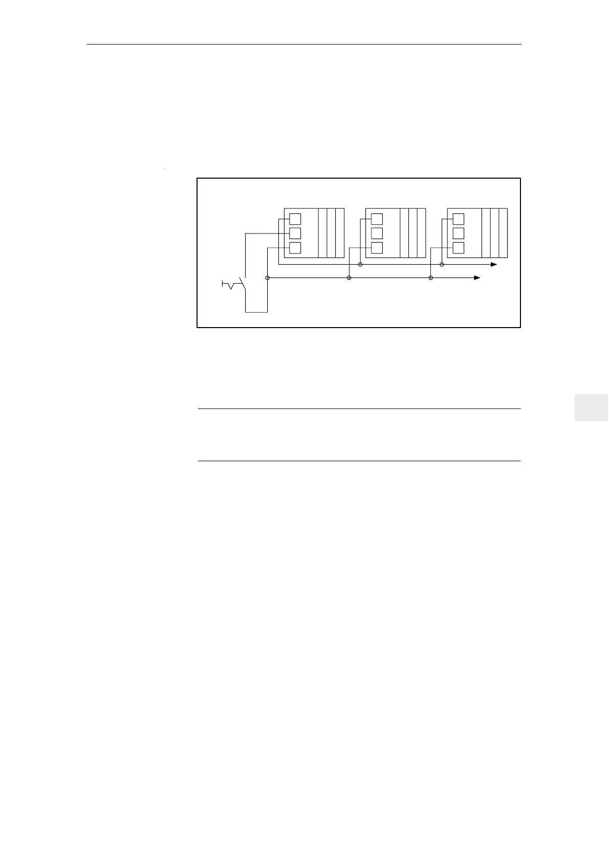
9.2.3 Connecting several NE modules to a main switch
A maximum of 6 terminal 48 can be connected in parallel, in order to power
down a maximum of 6NE modules with the leading contact of the main switch.
Max. cable length for 1.5 mm
2
cross section: 150 m (2–conductor cable)
Connection diagram:
19
9
48
NE module, drives
19
9
48
19
9
48
Main switch
Leading
contact
*)
*) *)
Additional units
It is not permissible that terminal 9 is connected
to terminal 48
NE module, drives NE module, drives
Fig. 9-3 Connection diagram of several NE modules at terminal 48
When enable terminals are connected in parallel to terminal 48, e.g. terminal 63
etc., the number of NE modules must be appropriately reduced as a result of
the higher current load at terminal 9.
Note
When the internal power supply fails at NE module 1, all of the other connected
NE modules and drives are inhibited. The drives “coast down” unbraked.
As an alternative to the limited current load capability of the internal power sup-
ply, the enable voltage can be taken via terminal 9 from an external 24 V PELV
power supply.
Terminals 19 of the NE modules must, in this case, be connected to the 0 V
reference potential (ground) of the external power supply.
9 Important Circuit Information

 Loading...


