4
05.01
4.2 Current de–rating
4-93
Siemens AG 2001 All rights reserved
SIMODRIVE 611 Planning Guide (PJU) – 05.01 Edition
4.2.5 Information on the motor–converter selection IM control digital
Two inverter clock frequencies can be parameterized: 4 kHz and 8 kHz.
Please observe the current de–rating at 8 kHz.
Table 4-9 Current load as a function of the inverter clock frequency
In/I
S6
/Imax
in A
In/I
S6
/Imax
in A
Imin
in A
Code
No.
Power
module
type
f
T
4.00 kHz
f
T
8.00 kHz
1
2
4
6
7
13
8
9
10
11
12
LT 8A
LT 15A
LT 25A
LT 50A
LT 80A
LT 108A
LT 120A
LT 160A
LT 200A
LT 300A
LT 400A
2.8/2.8/2.8
4.6/4.6/7.3
7.4/9.3/14.8
22/29/29
28/37/47
42/56/70
42/56/70
55/73/94
79/102/117
110/138/177
183/229/236
1.5/1.5/1.5
2.5/2.5/4.0
4.4/5.5/8.8
10/13/13
17/22/28
25/33/42
25/33/42
30/40/51
47/61/70
60/75/97
100/125/129
0.6
1.1
1.8
3.6
5.7
8.5
11.3
11.3
14.1
21.2
28.3
Dimensioning the series reactor, refer to Section 4.2.2
The individual power modules have different heatsink response temperatures.
Range, approx. 80 °C to 100 °C at the measuring point.
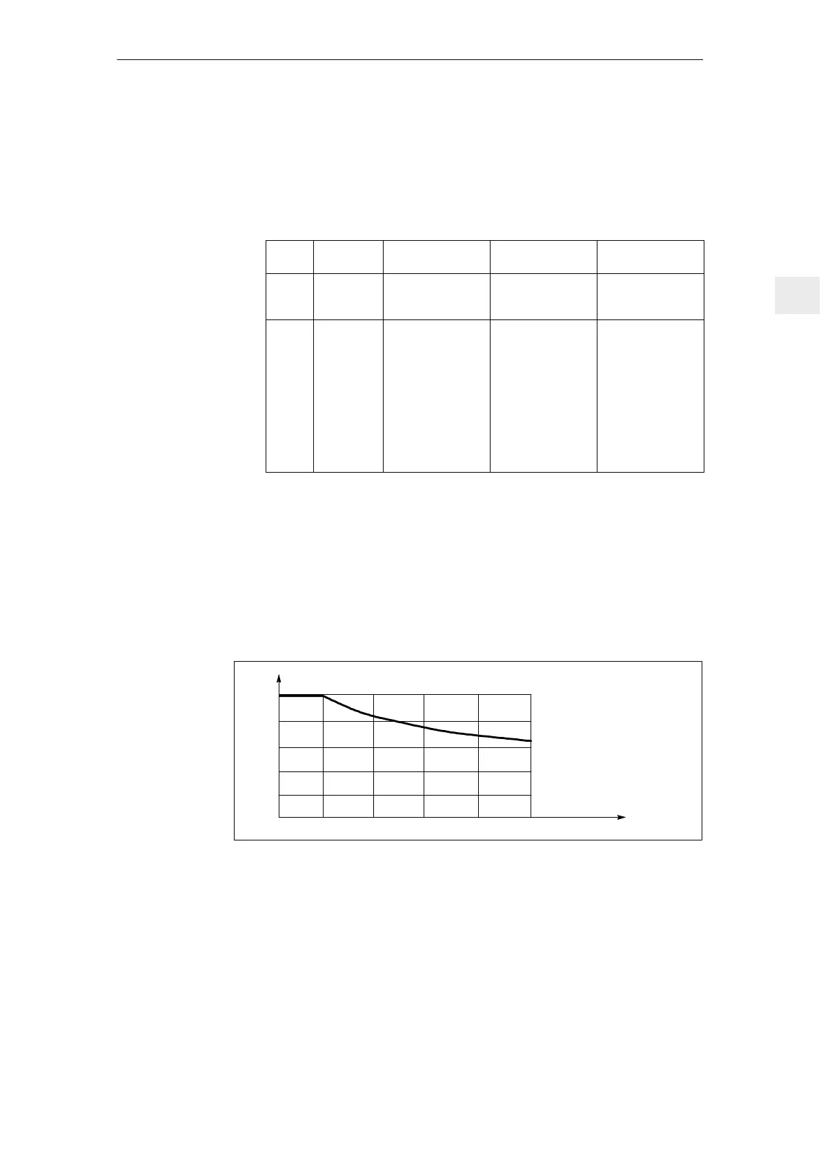
All of the specified load currents are valid up to an installation altitude of
1000 m. For installation altitude > 1000 m, the load currents must be de–rated
according to the diagram below.
100 %
0
1000
2000
Installation altitude (m)
80 %
60 %
40 %
20 %
0 %
3000 4000 5000
X
H
P
n
altitude
=x
H
P
n1000m
/100%
P
n
altitude
=x
H
P
s61000m
/100%
P
max.
altitude
=x
H
P
max.
1000m
/100%
Fig. 4-3 Current de–rating is dependent on the installation altitude
Caution: The currents I
n
, I
s6
and I
max
must be reduced in the same way.
å I
n
altitude
= x
H
I
n1000
m
/100%
å I
s6
altitude
= x
H
I
s61000
m
/100%
å I
max
altitude
= x
H
I
max1000
m
/100%
Example: PM 50 A: with MSD analog control: selected inverter clock
frequencies 6.3 kHz; installation altitude 2000 m
Heatsink tempera-
ture monitoring
Current de–rating
is dependent on
the installation
altitude
4 Power Modules

 Loading...


