6
05.01
6.1 Function overview and settings
6-165
Siemens AG 2001 All rights reserved
SIMODRIVE 611 Planning Guide (PJU) – 05.01 Edition
6.1 Function overview and settings
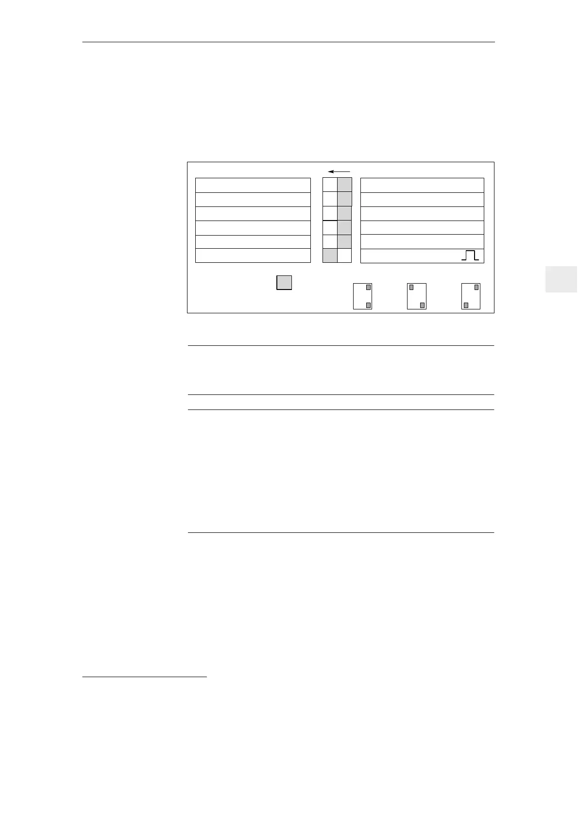
Switch S1 is provided on the upper side of the NE and monitoring module to set
the following functions (for 5 kW UI at the front panel):
ON: OFF:
V
supply
= 415 V"10 % V
DC
link
= 625 V
1)
Fault message
Regenerative feedback off
V
supply
= 400 V"10 % V
DC
link
= 600 V
1)
Regenerative feedback on
1
2
3
4
V
supply
= 480 V
+
6 %–10 %
Ready signal
S1
Controlled infeed off
Controlled infeed
5
6
Standard, refer to switch S1.1
Sinusoidal current operation
Square–wave current operation
Standard setting
ON 1
4
.
.
3–ph. 400 V AC
ON 1
4
.
.
3–ph. 415 V AC
ON 1
4
.
.
3–ph. 480 V AC
S1.1
S1.4
( on the line current side )
( on the line current side )
Fig. 6-4 DIL switch S1
Note
For a configuration for 480 V (S1.4= ON), the regenerative feedback is closed–
loop controlled. The setting of S1.5 is of no importance.
Notice
For I/R modules, Order number: 6SN114V–1VV0V–0VV1 Sinusoidal
operation is the basic setting.
For operation with filters, which are not listed in Table 6-1 the system must be
changed–over to squarewave current operation, in order that the filter is not
thermally overloaded.
Terminal 63 (pulse enable) and/or terminal 48 (start terminal, contactor control)
must be de–energized before the system is powered–up or powered–down
using the main switch or a line contactor!
OFF: I/R module, V
supply
= 400 V
"
10 %; V
DC
link
= 600 V
UI module V
supply
= 400 V
"
10 %; V
DC
link
= V
supply
1.35
Monitoring thresholds: (I/R, UI, monitoring modules)
PW on = 644 V; PW off = 618 V
U
DC
link
>> = 695 V
ON: I/R module V
supply
= 415 V
"
10 %; V
DC
link
= 625 V
UI module V
supply
= 415 V
"
10 %; V
DC
link
= U
supply
1.35
Monitoring thresholds: (I/R, UI, monitoring modules)
PW on = 670 V; PW off = 640 V
V
DC
link
>> = 710 V
PR = Pulsed resistor
1)
only possible for the I/R module, monitoring thresholds are increased for all NE modules.
General
information
Switch S1.1
6 Infeed Modules

 Loading...


