6
05.01
6-164
Siemens AG 2001 All rights reserved
SIMODRIVE 611 Planning Guide (PJU) – 05.01 Edition
DIL switch
Signal,
ready/
fault
I
2
t pre–alarm
and motor
overtemperature
Drive
enable
Pulse
enable
Reset Term. 112
setting–
up
3)
Term.
48
start
Checkback signal,
start inhibit
Equipment
bus
X151
Monit
oring
Voltage
controller
Current
setpoint
limiting
Current
controller
Pulse
generation
Gating
NS 1 X131
Electronics power supply
NS 1 NS 2
NS 1 NS 2
AS1 AS2112 48 19
FR–
9R15151044457
MN24N15P15P24
639964
FR+
Safety relay, start inhibit
Power supply and
signals
Equipment enable
V
act
5.372 73.1 73.2 74 5.25.1
DC link
sensing
V
mot
= 600V/625V
6
2)
1
1)
S1
2
1)
3
1)
4
1)
5
1)
Control
unit
I
act
T
max.
power
module
P600
M600
Line supply
rectification and
synchronization
DC link pre–
charging
circuit
Signal,
line contactor
Commutating
reactor
1) Status when supplied, OFF
2) Status when supplied, ON
3) Jumpers closed when supplied
Term. 1U1–2U1, 1V1–2V1, 1W1–2W1
Term. 9–112–48
Term. NS1–NS2
M500P500
4)
1W1 2W1 1V1 2V1 1U1 2U1U1 V1 1 W
L1 L2 L3
Line supply 3–ph. 400 V
AC (415/480V)
113 111 213
X131
PE
PE1L2
L2
L1
L1
Line supply 2–ph. 400V AC
(415/480V)
F1, F2
NS 2
Pre–charging
contactor
Line contactor
3)
3)
Setting, refer to
Section 6
5)
6)
4) Jumper
open when supplied
5) Terminals L1, L2 only for I/R modules
80 and 120 KW
6) Term. 113 not available for
5 and 10 KW UI modules
AB
100 k
AB
DC link controller
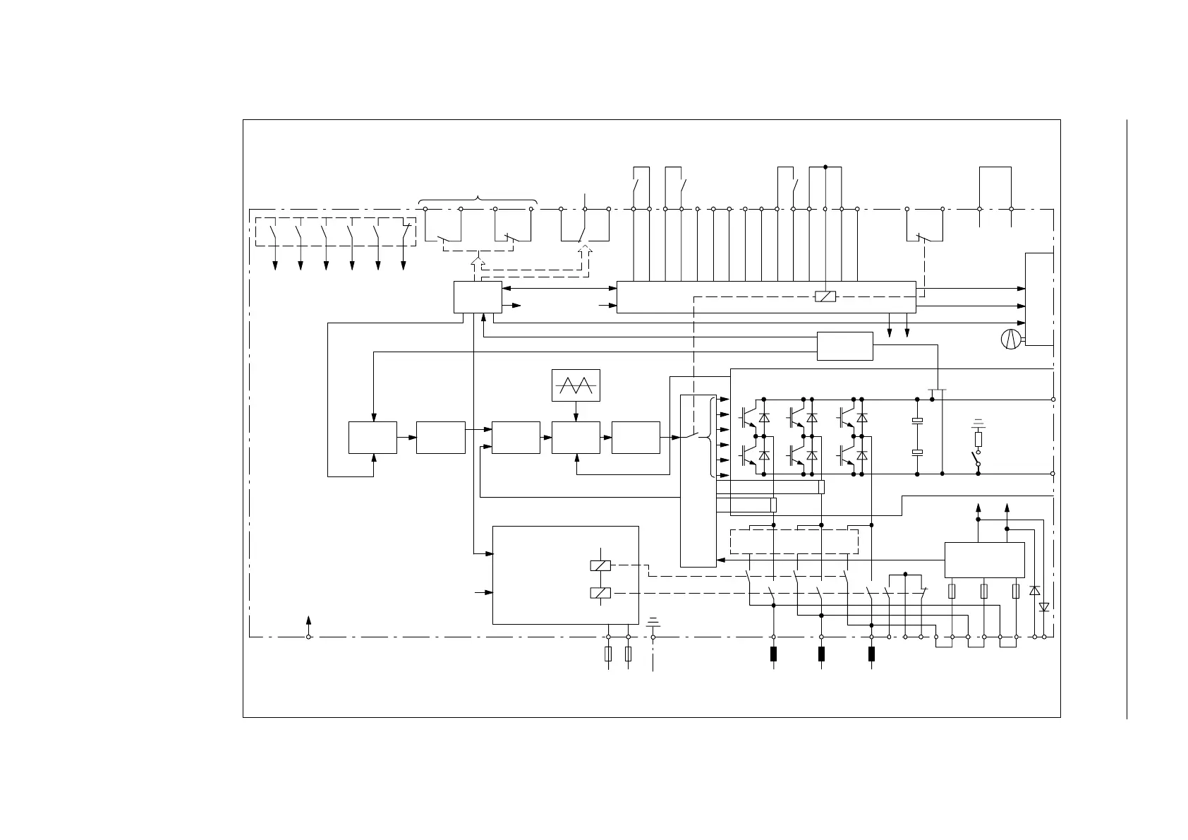
Fig. 6-3 Block diagram, line supply infeed module (I/R)
6 Infeed Modules

 Loading...


